Die Casting Surface Finish Standards: Ra, RMS, and How to Specify
Why Surface Finish Specification Matters
Surface finish is one of the most commonly misunderstood specifications on die cast parts. Engineers often specify finishes that are either:
- Unachievable in die casting (e.g., mirror finish Ra 0.05 µm from as-cast)
- Overspecified relative to function (e.g., Ra 0.8 µm when Ra 3.2 µm would work)
- Ambiguous (e.g., “smooth finish” without a numerical specification)
The result is either:
- Excessive cost from unnecessary finishing operations
- Failed inspection because the part cannot meet the spec
- Quality disputes between supplier and customer about what was actually specified
This article covers the standards, the achievable ranges, and the best practices for specifying surface finish on die cast parts.
Surface Finish Standards
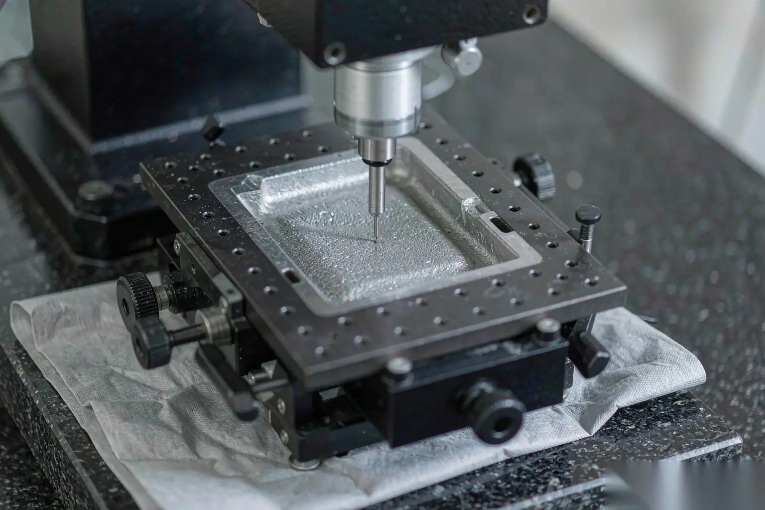
Ra (Arithmetic Average Roughness)
The most common standard globally. Ra is the arithmetic average of the absolute values of the surface profile deviations from the mean line, measured over a defined sample length.
Unit: micrometers (µm) or microinches (µin)
- 1 µm = 39.37 µin
- 1 µin = 0.0254 µm
Typical Ra values for die cast parts (as-cast):
- A380 aluminum: 1.6-6.3 µm (64-250 µin)
- A384 aluminum: 1.0-3.2 µm (40-125 µin)
- Zinc (Zamak): 0.8-1.6 µm (32-64 µin)
- After shot blasting: 1.6-3.2 µm (64-125 µin)
- After polishing: 0.1-0.8 µm (4-32 µin)
RMS (Root Mean Square Roughness)
An older US standard, still used in some industries. RMS is approximately 1.11 times Ra.
Conversion: RMS = 1.11 × Ra (approximately)
When to use: primarily in legacy US specifications, aerospace, and some military standards. New specifications should use Ra.
N-Grades (ISO 1302)
ISO roughness grades (N1 to N12) are sometimes used in European specifications. Each grade corresponds to a range of Ra values:
- N4: Ra 0.2-0.5 µm
- N5: Ra 0.4-0.8 µm
- N6: Ra 0.8-1.6 µm
- N7: Ra 1.6-3.2 µm
- N8: Ra 3.2-6.3 µm
- N9: Ra 6.3-12.5 µm
- N10: Ra 12.5-25 µm
For die cast aluminum, N7-N9 is the typical as-cast range.
Visual vs Measured
A common mistake is to specify a visual appearance (“matte”, “satin”, “mirror”) without a measured specification. Visual appearance is subjective and varies with lighting. Measured Ra is objective and reproducible.
Best practice: specify a measured Ra value AND a visual standard reference (e.g., a comparison sample or photo) for parts with critical appearance.
Achievable Surface Finishes by Process
| Process | As-Cast (Ra) | After Deburr (Ra) | After Polish (Ra) | After Anodize (Ra) |
|---|---|---|---|---|
| HPDC (A380) | 1.6-6.3 µm | 1.6-6.3 µm | 0.2-1.6 µm | 0.4-1.6 µm |
| HPDC (A384) | 1.0-3.2 µm | 1.0-3.2 µm | 0.1-0.8 µm | 0.2-1.0 µm |
| Cold-chamber (A380) | 1.6-6.3 µm | 1.6-6.3 µm | 0.2-1.6 µm | 0.4-1.6 µm |
| Zinc (Zamak) | 0.8-1.6 µm | 0.8-1.6 µm | 0.1-0.4 µm | n/a |
| Permanent mold | 3.2-12.5 µm | 3.2-12.5 µm | 0.4-1.6 µm | 0.8-1.6 µm |
| Sand casting | 6.3-25 µm | 6.3-25 µm | 0.8-3.2 µm | 1.6-3.2 µm |
The as-cast finish varies significantly by process. Sand casting is the roughest, zinc die casting is the smoothest.
What the Surface Finish Looks Like
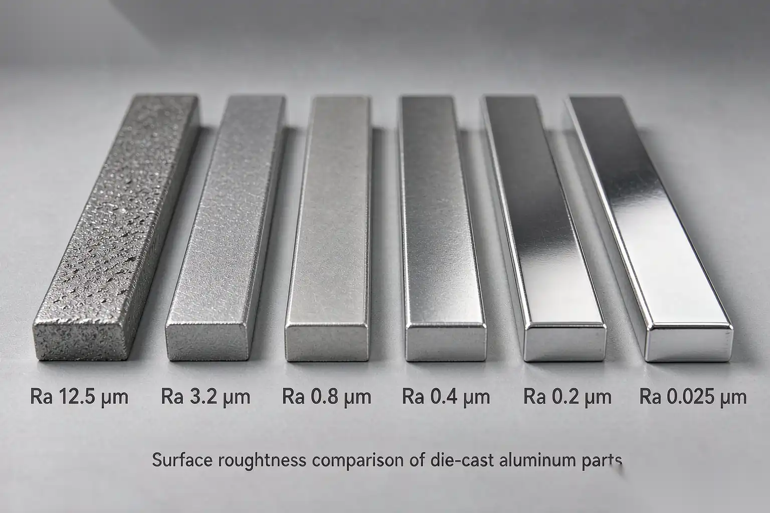
| Ra (µm) | Visual Appearance | Typical Application |
|---|---|---|
| 0.05 | mirror | not achievable in die casting |
| 0.1 | near-mirror | premium consumer products after polishing |
| 0.2 | very smooth | premium consumer, optical |
| 0.4 | smooth | consumer electronics, decorative |
| 0.8 | satin | consumer products, lighting |
| 1.6 | matte | general industrial, lighting |
| 3.2 | matte | typical as-cast aluminum |
| 6.3 | rough | typical as-cast, less cosmetic |
| 12.5 | very rough | sand casting, hidden parts |
| 25 | coarse | sand casting, structural only |
For most die cast parts, the as-cast finish (3.2-6.3 µm) is acceptable for non-cosmetic applications. For cosmetic parts, additional finishing (polishing, anodizing) reduces the finish to 0.4-1.6 µm.
How to Specify Surface Finish on a Drawing
Best practices:
1. Specify the Ra Value
Use the standard Ra symbol with a numerical value:
“`
Ra 1.6
─────────────
“`
2. Specify the Sampling Length
The default sampling length is 0.8 mm. For rough surfaces, use a longer sampling length (2.5 mm or 5.0 mm) to capture the full roughness.
3. Specify the Cutoff (λc)
The cutoff is the filter wavelength used to separate roughness from waviness. Standard cutoffs are 0.08 mm, 0.25 mm, 0.8 mm, 2.5 mm, and 8.0 mm. The choice depends on the surface roughness:
- Ra < 0.1 µm: λc = 0.08 mm
- Ra 0.1-2.0 µm: λc = 0.25 mm or 0.8 mm
- Ra 2.0-10.0 µm: λc = 0.8 mm or 2.5 mm
- Ra > 10.0 µm: λc = 2.5 mm or 8.0 mm
4. Specify the Direction (If Critical)
Surface finish varies with measurement direction. If the direction matters, specify it:
“`
Ra 1.6
╱ perpendicular to machining direction
“`
5. Specify the Surface Treatment
If the surface will be finished (anodized, polished, etc.), specify the finished surface, not the as-cast:
- “Surface to be polished to Ra 0.4 µm before anodizing”
- “Surface to be anodized to Type II, natural finish”
6. Avoid Subjective Terms
Avoid terms like “smooth”, “matte”, “satin” without numerical specifications. These are subjective and lead to disputes.
Common Surface Finish Mistakes
Specifying Mirror Finish on As-Cast
A drawing that calls for “mirror finish” or “Ra 0.05 µm” on an as-cast surface is impossible. The finishing process to achieve this adds significant cost (multi-step polishing, hand buffing, possibly plating).
Specifying the Same Finish on All Surfaces
Most parts have some cosmetic surfaces and some hidden surfaces. Specify the cosmetic surfaces separately; let the hidden surfaces be as-cast.
Confusing RMS and Ra
A specification of “RMS 32” is approximately “Ra 28” (32/1.11), not “Ra 32”. When converting, always use the correct ratio.
Not Specifying the Sampling Direction
Surface finish varies with direction. A surface polished in one direction will have a different Ra perpendicular to that direction. If the direction matters, specify it.
Forgetting the Finishing Process
The surface finish depends on the finishing process. Specifying Ra 0.4 µm without specifying the finishing process (polishing + anodizing, or polishing only) leaves the supplier to guess.
Surface Finish Verification
Measurement Methods
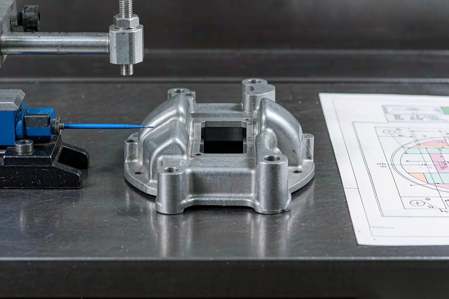
- Contact profilometer: the standard method, uses a stylus dragged across the surface
- Optical profilometer: non-contact, uses light interference
- Visual comparison: comparison to a reference sample, subjective
- Atomic force microscopy (AFM): for very smooth surfaces, expensive
Sampling
For a die cast part, measure Ra at multiple locations to get a representative value. Common practice:
- 3-5 measurements per part at defined locations
- Report the average and the range (not just the average)
- Define the location of each measurement on the drawing or in the inspection plan
Acceptance Criteria
For most die cast parts, the acceptance criterion is:
- Average Ra within specification
- No individual measurement exceeds 1.5x the specified Ra (roughness spikes)
- No visible defects (scratches, pits, inclusions)
For critical cosmetic parts, additional criteria may apply (no visible defects under specific lighting, color uniformity, etc.).
How to Reduce Surface Finish Cost
For cosmetic parts, the cost of achieving a specific finish can be significant. Ways to reduce cost:
- Relax the Ra specification where function allows. Ra 0.8 µm is much cheaper than Ra 0.2 µm.
- Specify different finishes on different surfaces. Hidden surfaces can be as-cast.
- Use the natural alloy color (clear anodizing) instead of dyed color (which hides surface defects less well).
- Choose a smoother-casting alloy. A384 gives smoother as-cast than A380.
- Use a textured die surface (EDM, chemical etching) for matte finishes instead of polishing.
- Invest in die polishing. A well-polished die produces smoother as-cast parts, reducing finishing work.
Measuring and Reporting Finish in Production
A surface finish specification is only as good as the measurement practice behind it, and most disputes trace to measurement, not to the surface. Three rules make the number trustworthy. First, fix the instrument and its parameters in the inspection plan: a contact profilometer with a stated cutoff and evaluation length, or an optical instrument with the same settings — because Ra measured with a 0.25 mm cutoff is not comparable to Ra measured at 2.5 mm, and both are legitimate numbers. Second, fix the locations: mark three to five defined spots on the drawing, aligned with how the part actually orients in service, and record each value — a single average hides the localized rough patch that becomes the customer complaint. Third, fix the direction relative to the last finishing pass, since a polished surface measured across the polishing direction reads rougher than along it.
Calibration closes the loop: a profilometer checked weekly against a reference specimen is an instrument; one checked annually is a hypothesis.
Reporting discipline matters as much as measuring discipline. Ship the values with the parts — location-tagged, instrument-identified, dated — and disagreements shrink to cases that genuinely deserve disagreement.
DZ Machinery lives inside this loop. Our polishing cells are qualified not by how the first article looks but by tracked Ra trends across production runs, measured at fixed points with fixed parameters, and our customers receive those trend lines with their shipments. When both the finishing cell and the customer’s incoming inspection measure the same way, “the finish drifted” stops being a debate and becomes a datapoint — usually with a cause attached the same week.
A Short Annotated Example of a Good Finish Callout
Putting the guidance into one concrete example: a consumer enclosure face is specified as “Ra 0.8 max, measured at three points shown on the drawing, cutoff 0.8 mm, measured parallel to the last polishing pass, after polishing and prior to Type II anodize, black, matte; reference approval sample DZ-A-1147”. Every element of that sentence does work: the numerical limit defines acceptance, the measurement points prevent cherry-picking, the cutoff makes values comparable across labs, the direction removes anisotropy ambiguity, the process stage states where in the chain the check applies, and the reference sample replaces a paragraph of adjectives with a physical object everyone can hold.
Compare it with the callout it replaces: “Surface to be smooth and uniform.” The first sentence costs ten minutes to write and prevents a year of disputes. The second costs nothing to write and guarantees at least one.
FAQ About Die Casting Surface Finish
What is the typical as-cast surface finish for A380?
Ra 1.6-6.3 µm (64-250 µin). The exact value depends on the die surface, the alloy, the process parameters, and the location on the part. Cosmetic surfaces are usually 1.6-3.2 µm; less cosmetic surfaces are 3.2-6.3 µm.
Can you achieve a mirror finish on a die cast aluminum part?
Yes, with multi-step polishing and buffing. The process is: 80-120 grit to remove surface defects, 220-320 grit to refine, 400-600 grit to smooth, then buffing with rouge compound for final gloss. Expect 30-60 minutes per square meter of surface for hand work.
What is the difference between Ra and RMS?
RMS is approximately 1.11 times Ra. The two standards measure similar surface properties but use different mathematical formulations. New specifications should use Ra.
Can a textured finish be specified for die cast parts?
Yes. Textured finishes (EDM texture, chemical etching, sandblasting) are commonly used for matte or anti-glare surfaces. Specify the texture depth and pattern, not just Ra.
A Realistic Surface Finish Strategy
The right surface finish strategy depends on the part’s function, appearance, and cost target:
- Hidden parts: specify “as-cast, no finish required” — saves cost
- Industrial parts: specify “as-cast, light bead blast for appearance” — minimal cost
- Consumer parts: specify “polished to Ra 0.8 µm, then anodized or powder coated” — moderate cost
- Premium consumer parts: specify “polished to Ra 0.4 µm, then anodized Type II with color” — higher cost
- Reflective parts: specify “polished to Ra 0.1 µm, then chrome plated” — highest cost
The cost increases dramatically as the Ra specification gets tighter. Specify the loosest acceptable finish.
At DZ Smart Manufacturing, our robotic polishing cells produce consistent surface finishes for die cast parts across consumer, industrial, and automotive applications. If you are specifying surface finish for a new die cast part and want feedback on what is achievable and what it will cost, our engineering team can review your drawing and provide a finish recommendation.