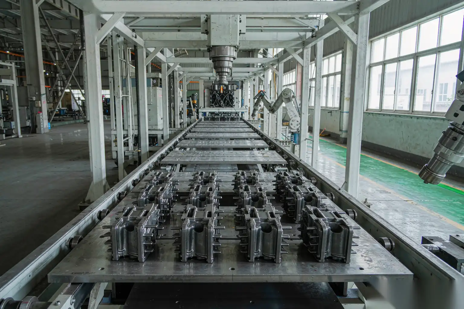
Die Casting Secondary Operations: A Routing Sheet With Real Cycle Times, Forces and Costs
Ejection is not the end of the process, it is the middle. On a plain structural bracket the casting operation might be 55% of the delivered cost; on a polished and plated faucet body the casting is 20-25% and everything after the die is the rest. Yet most cost models treat secondary operations as a single “finishing” line item with a guess in it. This article replaces the guess with a routing sheet: every station from the trim press to the pallet, with the parameters that actually govern it, the failure modes, the acceptance criteria and an indicative cycle time and cost.
The routing below assumes a cold-chamber aluminium casting in the 0.2-3.0 kg range. Zinc hot-chamber parts run a similar sequence with lower forces and no gate sawing in most cases.
Why secondary operations dominate the cost
Three structural reasons, and they compound:
- The casting is not a finished shape. It arrives with a biscuit, runners, overflows, a parting line witness, flash at every slide and ejector pin, gate scars, ejector pin marks of 0.05-0.30 mm, and die lubricant residue.
- The cosmetic surface is made, not cast. A chrome or PVD finish requires a substrate at Ra 0.05 µm or better with zero visible porosity. That is eight to twelve abrasive stages away from the as-cast surface.
- Variation from shot to shot forces manual handling. As-cast flash can vary 0.05-0.50 mm on the same part between the first shot of a shift and the three-hundredth. A fixed-path machine cannot absorb that; a human can, which is why these stations stay manual.
That third point is where automation either works or fails, and it is why the equipment architecture matters more than the brand.
Separating the casting from the shot
Trim press
The trim die shears the biscuit, runner and overflows off in one stroke. Get the tonnage and the clearance wrong and you will bend the part or leave a 0.5 mm burr that costs more downstream than the trim die did.
| Parameter | Typical value | Notes |
|---|---|---|
| Trim force | Area of shear (mm²) x shear strength; for aluminium use 150-200 N/mm² | Example: 600 mm perimeter x 3 mm thick x 180 N/mm² = 324 kN ≈ 33 t |
| Press capacity | 20-50 t small parts, 60-150 t medium, 150-300 t large structural | Size at 1.5-2.0x calculated force for flash variation and die wear |
| Punch-to-die clearance | 0.03-0.08 mm per side, or 3-5% of stock thickness | Too tight = die galling; too loose = rolled burr |
| Ram speed | 100-400 mm/s approach, 20-60 mm/s cutting | Slow cutting reduces burr height |
| Cycle time | 8-20 s including load and unload | Robot load adds 3-6 s |
| Die material | D2 or A2 at 58-62 HRC, or H13 for hot trimming | Hot trim at 150-250°C reduces cracking on high-Si alloys |
Hot trimming versus cold trimming is a real decision. Trimming above 150°C cuts the required force by 20-35% and greatly reduces the risk of tearing at the gate on high-silicon alloys, but it requires the part to go straight from the die to the press, and it makes dimensional control harder because the part shrinks after the trim. Cold trimming after a controlled cool to below 80°C is dimensionally safer and easier to automate with a robot and a cooling conveyor.
Failure modes to watch: rolled burr at the trim line from excessive clearance; part distortion from unbalanced support; gate tear-out leaving a 1-3 mm depression that later shows through a polished finish; and flash slivers that stick to the trim die and mark the next part. An automatic die lubrication or air-blow between strokes is not optional at volume.
Band sawing gates, risers and LP stalks
HPDC gates are usually trimmed; low pressure risers, gravity feeder heads and large biscuit gates are sawed because the section is too heavy for a trim die.
| Parameter | Typical value |
|---|---|
| Blade | Bi-metal or carbide-tipped, 2-3 mm kerf, 3-6 TPI for thick sections |
| Blade speed | 800-2,000 m/min bi-metal; 1,500-3,000 m/min carbide |
| Feed rate | 20-120 cm²/min aluminium, set by chip load |
| Cut length per cycle | 15-120 s for a 20-80 mm section |
| Cutting fluid | Emulsion 5-8%, flood or through-blade minimum quantity |
| Blade life | 8-20 h of cutting time, or 300-1,500 cuts, depending on section and alloy |
The fixture governs everything here. The part must be supported so that the falling gate cannot pull material out of the casting as the blade exits, and the cut must be located from machined or cast datums, not from the flash. On a sanitary body the saw cut is normally taken on the non-cosmetic feeder boss, leaving 1-3 mm of stock for the grinding station.
Bulk conditioning and machining
Shot blasting and vibratory finishing
Purpose: uniform the surface, remove parting line scale and release agent residue, and break the sharp edges so that the grinding station sees a consistent input.
| Parameter | Shot blast | Vibratory |
|---|---|---|
| Media | Steel shot 0.2-0.8 mm, or ceramic / glass bead 0.1-0.5 mm | Ceramic or plastic cones, 10-40 mm |
| Intensity | Almen 0.10-0.30 mmA for cleaning only | — |
| Amplitude / speed | Wheel 60-80 m/s | 2-4 mm amplitude, 900-1,500 rpm |
| Cycle | 30-180 s in a hanger or tumble blast | 10-45 min |
| Resulting Ra | 3.2-8.0 µm | 0.8-3.2 µm |
| Edge break | 0.05-0.20 mm | 0.10-0.40 mm |
| Best for | Large parts, heavy flash removal | Small parts, batch processing, pre-polish surfaces |
Two cautions. First, shot blasting a surface that will later be polished to a mirror is usually a mistake: the blast folds and smears metal over pores rather than removing them, and those folded pores open during polishing or plating and appear as pinholes. For pre-plate work, use abrasive belt or flap-wheel conditioning instead of blast. Second, media must be separated from the parts completely before machining; a single embedded steel shot will destroy a cutting edge.
CNC machining and datum strategy
Most castings get at least one machining operation: sealing faces, bores, mounting pads, threads. The casting tolerance envelope and the datum strategy decide the scrap rate.
| Parameter | Typical value |
|---|---|
| As-cast tolerance | ISO 8062 CT5-CT7 for HPDC; CT7-CT8 for LP and gravity |
| Machining stock | 0.5-1.0 mm on faces up to 100 mm; 1.0-2.0 mm above 100 mm; 2-3 mm on LP gate pads |
| Datum scheme | 3-2-1, located on non-cosmetic surfaces and stable core-formed features |
| Datum repeatability target | Under 0.05 mm on the primary datum, 0.10 mm on secondary and tertiary |
| Clamping | Hydraulic or pneumatic, 2-6 kN per clamp, supported directly over a wall or boss |
| Cutting speed | 200-400 m/min carbide, 400-900 m/min PCD for A380 and ADC12 |
| Cycle time | 20-180 s per part depending on feature count |
The most common datum error is locating on a cast surface that is formed by a moving slide or by two die halves, because those features shift by the die clearance, which grows over tool life. Locate from core-formed features and from the same die half wherever possible, and state that in the drawing with a datum target rather than leaving it to the shop.
Chip evacuation and coolant filtration matter more than on billet work: casting swarf carries silicon and iron intermetallics that abrade the machine ways and the coolant pump. Budget coolant filtration to 25-50 µm and a swarf briquetting or centrifuging step if you are machining more than a few hundred kilograms per day.
Tapping, threading and inserts
| Parameter | Roll-formed (chipless) thread | Cut thread | Threaded insert |
|---|---|---|---|
| Suitable alloys | A356, low-Si, elongation above 5% | A380, ADC12, any | All, for serviceability |
| Pre-hole diameter | 0.55-0.65 x pitch below nominal, alloy-specific | Standard tap drill | — |
| Engagement length | 2.0-2.5 x diameter in aluminium | 2.0-3.0 x diameter | — |
| Tap speed | 10-30 m/min | 8-20 m/min | — |
| Tool life | 50,000-150,000 holes | 20,000-60,000 holes | — |
| Pull-out strength, M6 in A380 | 12-18 kN at 15 mm engagement | 10-15 kN | 15-25 kN with a helical insert |
| Cycle time | 2-6 s per hole | 3-8 s per hole | 8-20 s per insert |
Roll-formed threads are stronger because the material is cold-worked rather than cut, and they produce no chips to contaminate the assembly. They are not usable in low-elongation, high-silicon HPDC alloys without trial, because the material will not flow and the lobes crack. Cut threads in A380 need a sharp, high-helix tap and generous lubricant; the failure mode is a packed flute and a broken tap in a blind hole, which usually means the part.
For service threads and for soft alloys, use a wire thread insert or a self-tapping insert, and specify the installation torque and the proof torque on the drawing.
Deburring the parting line and flash
This is the highest-labour station in most plants and the one with the widest quality spread. The input is a parting line witness of 0.05-0.30 mm plus slide and ejector flash, and the output requirement is normally an edge break of 0.1-0.5 mm with no visible witness line on a cosmetic surface.
| Parameter | Manual | Robotic cell with compliant spindle |
|---|---|---|
| Cycle time per part | 45-120 s | 25-50 s |
| Operators per shift | 4-12 depending on volume | 1 operator tending 2 cells |
| Contact force control | Operator judgement, 5-60 N and drifting | Force-controlled float, set 5-40 N, held to ±1-2 N |
| Edge consistency | ±0.2-0.4 mm across a shift | ±0.05-0.10 mm over 500,000 cycles |
| Scrap from over-grinding | 1-4% | Under 0.5% |
| Media | Flap wheel, belt, fibre disc | Same, with automatic media change and wear compensation |
| Dust exposure | Operator in the plume | Enclosed, extracted at 3,000-6,000 m³/h |
| Repeatability after 8 h | Degrades with fatigue and PPE discomfort | Unchanged |
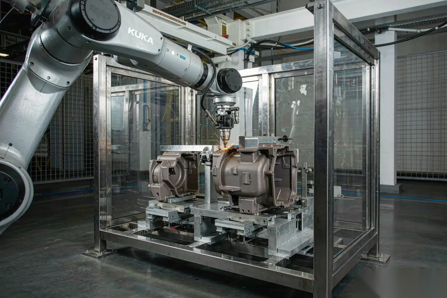
The engineering content that makes a robotic cell work is not the robot, it is the compliant tool. A floating pneumatic or servo spindle holds a constant normal force while the part varies, so a fat casting is not gouged and a thin one is not missed. Add automatic media change (four to eight positions), a wear compensation routine that indexes the contact point as the wheel diameter drops, and a two- or four-station rotary table so that load and unload happens in parallel with grinding. That combination is what turns a 90-second manual station into a 35-second automated one with one operator instead of six.
Labour arithmetic, stated plainly: a manual cell at 75 s per part producing 2,400 parts per two-shift day needs roughly 6 operators per shift, 12 for two shifts. A two-cell automated line at 35 s per part with one operator per shift produces more than that with 2 operators. At a fully loaded cost of 12,000-25,000 USD per operator per year depending on country, the direct labour saving is 120,000-300,000 USD per year, before counting the 1-3% scrap reduction and the elimination of a dust exposure and a repetitive-strain job. Typical payback on the cell is 12-24 months, and shorter where labour is expensive or where the scrap rate on cosmetic parts is already above 3%.
DZ Machinery builds exactly this cell, with the fixture, the compliant spindle, the enclosure and the dust extraction sized to the part family rather than to a machine model. Background on the mechanism is in our how to deburr aluminum die castings with automation article.
Grinding and pre-plating polishing
Grinding stages and grit progression
Grinding is not one operation, it is a ladder. Skipping a rung is the single most common cause of a poor polish: the next stage cannot remove the scratch pattern of the previous one, and the defect only appears after plating.
| Stage | Abrasive | Grit | Contact pressure | Purpose | Resulting Ra |
|---|---|---|---|---|---|
| 1. Gate removal | Zirconia or ceramic belt | 36-60 | High, 30-60 N | Bring the gate scar flush | 6-12 µm |
| 2. Blending | Aluminium oxide belt | 80-120 | Medium, 20-40 N | Remove stage 1 pattern | 2.5-5 µm |
| 3. Fine grind | Aluminium oxide or SiC belt | 180-240 | Medium, 15-30 N | Uniform the surface | 1.0-2.0 µm |
| 4. Pre-polish | Non-woven abrasive or belt | 320-400 | Low, 10-20 N | Prepare for cut buff | 0.4-0.8 µm |
| 5. Greasing | Non-woven with compound | 500-600 | Low, 8-15 N | Close shallow porosity | 0.15-0.30 µm |
Belt speed is 20-35 m/s for aluminium, and the belt must be run with a lubricant or a greaseless compound to avoid loading; aluminium loads a belt in 30-90 seconds if it runs dry. Each stage should remove 1.5x to 2x the depth of the previous scratch pattern, and the scratch direction should be rotated roughly 90° between stages so that the operator or the vision system can confirm the previous pattern is gone.
Pre-plating polishing
For chrome, PVD or bright anodize, a two-stage buff follows the grind ladder.
| Stage | Wheel | Compound | Speed | Ra achieved |
|---|---|---|---|---|
| Cut buff | Treated cotton or sisal, 200-350 mm | Tripoli / black emery, applied automatically every 20-60 s | 25-35 m/s peripheral | 0.10-0.20 µm |
| Colour buff | Loose cotton, 300-400 mm | White or green rouge | 30-40 m/s peripheral | 0.02-0.05 µm |
| Final satin (if required) | Non-woven flap | Grease-less | 15-25 m/s | 0.4-0.8 µm, directional |
Compound consumption is 1-4 g per part on a faucet body, applied by an automatic bar feeder rather than by hand, because hand application is the largest source of finish variation. Wheel wear is 0.5-2.0 mm per hour of running and must be compensated by advancing the wheel, which is why the cell needs a wear compensation routine and a wheel dressing cycle.
Automatic polishing cells from DZ Machinery use multi-station rotary indexing with four to twelve buffing heads, automatic compound feed and servo compensation, and they are the standard solution for faucet bodies, zinc handles and lock plates. The quality argument is as strong as the labour one: a manual polisher produces a finish that varies across a shift, and on a mirror chrome part that variation is visible on the assembled product.
Coating, anodizing and plating flows
| Finish | Flow | Film thickness | Cycle | Indicative cost |
|---|---|---|---|---|
| Chromate / zirconium conversion | Clean, deoxidise, convert, dry | 0.1-1 µm | 5-15 min | Low |
| Powder coat | Blast or convert, pre-bake 200°C x 30 min, coat, cure 180-200°C x 15-20 min | 60-120 µm | 45-90 min | Medium |
| E-coat | Clean, zirconium pretreatment, e-coat, bake | 15-35 µm | 40-70 min | Medium |
| Sulphuric anodize | Clean, etch, desmut, anodize 12-20 V, dye, seal | 8-25 µm | 60-120 min | Medium |
| Hard anodize | Anodize at 0-5°C, 25-60 A/dm² | 25-60 µm | 90-180 min | High |
| Decorative chrome | Polish, clean, zincate, Cu 15-30 µm, Ni 10-20 µm, Cr 0.3-1.0 µm | 25-50 µm total | 90-180 min | High |
The pre-bake before powder coating is not optional on die castings. Gas in shallow pores expands at the 180-200°C cure and blows pinholes through the film. Baking at 200-220°C for 30-60 minutes before coating lets the gas out and lets you repair the surface first.
Leak testing, inspection and packaging
Leak testing and acceptance
| Method | Parameter | Pass criterion |
|---|---|---|
| Air under water | 4-6 bar, 30-60 s | No continuous bubble stream |
| Pressure decay | 1.5x working pressure, 30 s measure | Decay under 1-2% of charge |
| Helium mass spec | 1e-6 to 1e-8 mbar·l/s | Application-specific |
| Dimensional CMM | Monthly or per shift sample | Cpk above 1.33 on critical-to-function features |
| Cosmetic inspection | 500-1,000 lux, 300-500 mm viewing distance, defined viewing time | Per an agreed limit sample board |
Agree the limit samples before production. A written finish specification without physical limit samples is how a plant ends up arguing about “acceptable” for a year.
Packaging
Specify it. Parts touching each other in a bulk box will scuff a polished or anodized surface in transit; the fix is either individual sleeving at 0.05-0.15 USD per part, or a thermoformed tray at 0.10-0.40 USD. For export, budget 3-8% of landed cost for packaging and palletisation, state the pallet standard and the stack height, and require a drop test and a vibration test on the first shipment.
Consolidated routing sheet
Indicative figures for a 0.8 kg A380 or ADC12 cosmetic housing, annual volume 120,000 pieces, two shifts.
| # | Operation | Cycle per part | Labour per part | Indicative cost, USD | Notes |
|---|---|---|---|---|---|
| 1 | Trim press, robot loaded | 15 s | 0.03 min | 0.06 | 60 t press, cold trim |
| 2 | Band saw gate | 25 s | 0.05 min | 0.09 | Carbide blade, 2 cuts |
| 3 | Shot blast, hanger | 40 s | 0.03 min | 0.07 | Steel shot 0.4 mm |
| 4 | CNC op 10 and 20 | 95 s | 0.08 min | 0.85 | Two machining centres, one operator on four |
| 5 | Tapping, 4 holes | 18 s | 0.02 min | 0.10 | Cut threads in A380 |
| 6 | Robotic deburr, 2 cells | 35 s | 0.02 min | 0.22 | One operator tending both cells |
| 7 | Robotic grind, 3 stages | 55 s | 0.03 min | 0.30 | 60-120-240 progression |
| 8 | Automatic polish, 2 heads | 60 s | 0.02 min | 0.28 | Cut and colour |
| 9 | Powder coat | 60 s line time | 0.04 min | 0.55 | Including pre-bake |
| 10 | Leak test and inspection | 30 s | 0.06 min | 0.14 | 100% leak, 10% dimensional |
| 11 | Pack, sleeve and palletise | 25 s | 0.08 min | 0.18 | Individual sleeve |
| Total | ~7.6 min | 0.46 min | ~2.84 | Excluding the casting itself and material |
Three notes on reading that sheet honestly:
- It assumes the cell is fed continuously. Any buffer below about 20 minutes of parts between casting and finishing will show up as lost output, because a die change or a furnace delay starves the robots.
- It assumes the as-cast variation is inside the window the cell was specified for. If flash swings beyond 0.5 mm or the parting line shifts more than 0.3 mm, no compliant spindle will hold the specified edge, and the trim die or the casting process is the thing to fix.
- It excludes the capital recovery, which is the point of the next section.
Read the labour column against a manual alternative: stations 6, 7 and 8 in a manual plant consume 0.15-0.25 min of direct labour each, and the whole routing would run 0.9-1.3 min of labour per part instead of 0.46. On 120,000 parts per year that is roughly 900-1,700 operator-hours, and the quality spread is wider at every one of those stations.
Where a turnkey line makes sense
Deburr, grind and polish are the three stations that are (a) labour heavy, (b) dusty and ergonomically poor, and (c) the largest source of cosmetic rejects. They are also the three stations where a compliant-force robot beats a human on consistency, because the human is being asked to hold ±0.1 mm of metal removal while standing in a dust plume. That is why we build these as cells rather than as standalone machines: the fixture, the media management, the dust and explosion extraction, the part transfer between stages and the cycle-time study are one problem, not five.
For sanitary plants the whole upstream chain is worth automating as a line: core shooting, low pressure or gravity casting, band saw, CNC, robotic grinding, automatic polishing and inspection, with a single handling philosophy and a single buffer strategy. DZ Machinery builds that turnkey line, and we quote it from a cycle-time and yield model built on your part rather than from a machine list.
If you are costing a new programme or re-costing an existing one, send us the part drawing, the alloy, the required finish class, the annual volume and your current station-by-station manning. We will return a routing sheet with modelled cycle times, consumable cost per part and a labour comparison against your present cell, including the fixtures and extraction that a quoted machine price usually leaves out.