Selecting Die Casting Machine Tonnage and Shot Size
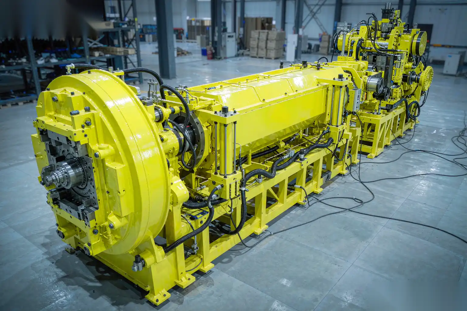
Choosing a die casting machine starts with two numbers that are often confused: the clamp tonnage and the shot size. Tonnage is the force that keeps the die halves from opening under injection pressure. Shot size is the mass of metal the machine can deliver into the cavity in one cycle. Get either one wrong and you pay for it on every part, either in flash and scrap from undersizing or in idle capital and energy from oversizing.
This article is a practical selection guide for the process engineer quoting a new part or rebalancing a cell. We derive required lock force from projected area and specific pressure, explain the margin you should hold, relate shot weight to cold-chamber capacity and biscuit, size the plunger and its fill ratio, and show how the machine choice feeds cycle time, die size, and cost. A worked table maps part weight to tonnage so you can sanity-check a quote.
The core equation: projected area times specific pressure
The die halves are held shut by the clamp. During injection, the molten metal pushes against every surface it touches, and the component of that pressure acting to open the die equals the cavity’s projected area multiplied by the specific (intensification) pressure at the cavity.
Required lock force, minimum:
F_lock (tonnes) = Projected area (cm2) x Specific pressure (kgf/cm2) / 1000
Or in more familiar terms:
F_lock (kN) = A_proj (mm2) x P_spec (MPa) / 1000
Projected area is the area of the cavity and any overflows and the sprue, as seen looking along the clamp axis, summed across all cavities. It is not the part surface area; it is the shadow the part casts on the parting plane. Designers forget overflows and runners all the time, then wonder why the die flashes.
Specific pressure is the cavity pressure at the end of injection, which for high-pressure die casting of aluminum commonly runs 40 to 80 MPa at the cavity, depending on the machine’s intensification and the gate. A conservative planning value for aluminum is to size against the machine’s rated specific pressure or 60 to 70 MPa, whichever the actual cavity sees.
Worked example: a single cavity with a projected area of 300 cm2 at 70 MPa cavity pressure.
F = 300 x 700 (kgf/cm2) / 1000 = 210 tonnes minimum
That part needs a machine rated for at least 210 tonnes of usable clamp, before any margin.
Why you hold a 20 to 40 percent margin over the calculated value
The calculated minimum is exactly that: the value at which the die just barely stays shut under ideal conditions. Real production is not ideal. You hold margin for several reasons:
- Cavity pressure is not perfectly uniform; local peaks at the gate can exceed the average specific pressure you used in the calc.
- Die temperature varies through a shift, changing thermal expansion and parting-line fit; a warm die flashes more easily.
- Plunger and intensifier wear raise the actual pressure the hydraulics must supply, eating into effective clamp.
- Multi-cavity tools accumulate tolerance; the largest cavity dominates the required force.
- You want headroom to raise injection pressure for fill without opening the die.
We recommend a usable clamp of 1.2 to 1.4 times the calculated minimum. Below 1.2x you are running on the edge and flash becomes a daily fight. Above 1.4x you are usually on a larger machine than the part needs, which is the oversizing problem addressed below.
Note “usable clamp,” not nameplate. Tie-bar stretch, platen deflection, and die height limits mean a 250 tonne machine may only deliver a usable 230 tonnes at your die height. Check the machine curve, not just the badge.
Shot weight versus cold-chamber capacity and the biscuit
Tonnage is only half the check. The machine must also deliver enough metal. Shot weight is the total mass injected per cycle: the part(s) plus the gate and runner plus the biscuit (the slug left in the cold sleeve after the plunger retracts).
For a cold-chamber machine:
Shot weight = Part mass x cavities + Runner/gate mass + Biscuit + Overflows
The biscuit is not optional. You need enough sleeve fill that the plunger does not bottom out in air and that a coherent slug remains to be ejected. A typical biscuit is 10 to 30 mm thick depending on sleeve diameter; its mass can be a meaningful fraction of small parts.
Two limits apply:
- Maximum shot capacity: the machine’s rated shot weight, usually quoted at a specific alloy density (often aluminum). Do not run above about 60 to 70 percent of rated capacity if you want consistent fill and shot-to-shot repeatability; pushing to 90 percent starves the sleeve of room to build pressure.
- Minimum shot: too small a shot in a large sleeve gives poor plunger control and variable biscuit, so a 400 tonne machine is a poor home for a 50 gram part.
Always total the metal honestly. A common quoting error is to size the machine on part weight alone and ignore that the runner and biscuit may equal or exceed the part mass on a small, thin component.
Plunger diameter and the 30 to 70 percent fill ratio
The cold-chamber sleeve diameter sets how much metal the plunger can push and at what velocity. A larger plunger moves more mass but at lower injection velocity for the same hydraulic power; a smaller plunger gives higher velocity, which thin-wall parts need, but holds less metal.
The key ratio is sleeve fill ratio: the volume of metal in the sleeve divided by the sleeve volume available at shot position.
Recommended fill ratio: 30 to 70 percent.
- Below 30 percent: too much air in the sleeve, gas entrainment and turbulent fill, porosity. Also poor plunger control.
- Above 70 percent: not enough plunger travel to reach the required injection velocity, and the biscuit gets thin and unstable.
- The sweet spot, 40 to 60 percent, gives clean acceleration and a stable biscuit.
Sizing the plunger:
- Compute total shot volume from shot weight and alloy density (aluminum about 2.4 to 2.7 g/cm3 liquid, use the solid density for mass planning plus shrinkage).
- Choose a sleeve diameter whose cross-sectional area, times the desired shot length (sleeve stroke), yields a fill in the 30 to 70 percent band.
- Confirm the resulting plunger velocity at your machine’s max injection rate meets the gate velocity the part needs (commonly 30 to 60 m/s at the gate for aluminum; thin-wall needs the high end).
Undersized plunger: cannot deliver enough metal, forces a too-thick biscuit or short sleeve, limits velocity. Oversized plunger: low velocity, sluggish fill, cold laps on thin sections. The fill ratio is the control that keeps both in range.
How undersizing causes flash and oversizing wastes capital
The two failure modes are mirror images, and both are expensive.
Undersizing (too little tonnage):
- The die opens a few microns at the parting line under peak pressure. Metal squeezes into that gap: flash.
- Flash grows with pressure and with die temperature, so it is inconsistent shot to shot.
- Inconsistent flash defeats robotic deburring, because the robot meets a different edge every cycle.
- Operators compensate by slowing injection or lowering pressure, which hurts fill and raises scrap for a different reason.
Oversizing (too much tonnage or an oversized sleeve):
- You buy a 500 tonne machine to make a 200 tonne part. The capital sits idle on capability you never use, and the floor space and energy bill are real.
- Larger machines have slower platen motion and longer idle strokes, nudging cycle time up even when the casting itself is small.
- A too-large sleeve on a small shot drops the fill ratio below 30 percent, hurting fill, so oversizing the machine can actually degrade the process if the sleeve is not also right-sized.
- Energy per shot scales with clamp and injection power; running a big machine for a small part wastes it on every cycle.
The right answer is a machine where the calculated clamp sits at 1.2 to 1.4x margin and the shot sits in the 40 to 60 percent fill band. That is the operating point where flash is low, fill is clean, and you are not paying for capacity you do not use.
Relation to cycle time and die size
Machine selection interacts with cycle time and die envelope in ways that surprise first-time quoters.
- Platen size limits die dimensions. A part that fits the tonnage but needs a die larger than the platen window will not mount. Check daylight, platen dimensions, and tie-bar spacing before committing.
- Larger machines generally have longer open-close and eject sequences; matching the machine to the part avoids adding dead time.
- Clamp speed and injection rate vary by machine class; a high-speed machine rated for thin-wall aluminum may let you drop wall thickness, which changes the projected area and tonnage requirement downward.
- Die temperature control (number and size of cooling channels) is set by the part, not the machine, but the machine’s shot-end thermal management affects biscuit consistency, which loops back to fill ratio.
So tonnage and shot size are not standalone numbers; they are the center of a loop that includes die size, cycle time, and wall thickness. Improving one (thinner walls) reshapes the others (lower projected area, possibly higher injection velocity needed).
A practical part-weight to tonnage reference
The table below is a planning aid, not a substitute for the area-times-pressure calc. It assumes aluminum, single cavity, moderate overflows, and a 1.3x margin at roughly 60 to 70 MPa cavity pressure. Real values shift with geometry, cavity count, and gate pressure.
| Part mass (g) | Typical projected area (cm2) | Min calc lock (t) | Recommended machine (t) | Notes |
|---|---|---|---|---|
| 20 to 50 | 30 to 80 | 20 to 55 | 50 to 90 | Small, multi-cavity often better |
| 50 to 150 | 80 to 180 | 55 to 125 | 90 to 180 | Common bracket/enclosure range |
| 150 to 400 | 180 to 400 | 125 to 280 | 180 to 400 | Structural parts |
| 400 to 900 | 400 to 800 | 280 to 560 | 400 to 700 | Large housings |
| 900 to 2000 | 800 to 1500 | 560 to 1050 | 700 to 1300 | Big castings, slow cycle |
Use this to catch a quote that says a 50 gram part needs a 350 tonne machine, or that a 1 kg part fits a 180 tonne press. Both are red flags: one is oversizing, the other will flash.
For the broader high-pressure aluminum process context behind these numbers, see our high pressure aluminum die casting guide, which covers injection and gating assumptions used in the calc.
Cost implications and avoiding the wrong machine
The machine choice is the largest single capital decision on a die casting line, so getting tonnage and shot size right protects both quality and budget.
Cost levers the selection controls:
- Scrap from flash and cold laps, which the right tonnage and fill ratio suppress.
- Energy per shot, lower on a right-sized machine.
- Capital tied up in oversized presses that could be two cells instead of one.
- Cycle time, which moves with machine class and sleeve size.
Our aluminum die casting cost factors breakdown shows how machine selection flows into unit cost, and our die casting yield and scrap reduction guide shows how flash and fill problems, rooted in machine sizing, become scrap that compounds across a production run.
The discipline is simple to state and easy to skip: do the projected-area calculation, add the margin, total the real shot weight including biscuit and runner, and size the plunger for a 40 to 60 percent fill. Do that before signing the machine order and most first-article surprises disappear.
Soft CTA
DZ Machinery integrates die casting cells end to end and sizes the trim, robotic deburring, and polishing stations to the actual machine and part you run, not to a generic assumption. If you are quoting a new part or rebalancing an existing line, talk to our engineering team and we will check your tonnage, shot, and fill assumptions against the cell we would build around them.