Die Casting Gating System Design: Runner, Gate and Overflow Strategy
Why Balanced Fill Is More Than Geometric Symmetry
In high-pressure die casting the gating system is the only hydraulic interface between the shot cylinder and the cavity. Its job is to deliver molten aluminum at a controlled velocity and temperature to every point of the cavity before the metal freezes, while keeping entrained air, oxide and re-solidified biscuit below a defect threshold. A common failure mode among die makers is mistaking “balanced” for “symmetrical.” A symmetric runner layout with equal path lengths does not guarantee equal fill when cross-sections, local die temperature and vent capacity differ between branches.
We treat balancing as a flow-resistance problem, not a drafting problem. The design target is equal pressure and equal fill time at every gate. That means every branch must carry the mass flow its cavity needs while presenting the same effective resistance to the manifold. Resistance is dominated by the runner hydraulic diameter, the runner length, and the restrictive gate cross-section. If two identical cavities are fed by runners of the same cross-section but one is 40 mm longer, the longer branch sees a higher pressure drop and fills later. The late-filling cavity then pulls metal away from the earlier one, producing cold laps at the junction and inconsistent mechanical properties between the two parts.
The practical rules we apply at the gate design stage:
- Compute total shot volume (cavity + runner + overflow + biscuit) and divide by the target fill time, typically 15-45 ms for aluminum at 30-60 m/s gate velocity.
- Size the main runner so its velocity stays below roughly 10 m/s; above that, oxide film generation and premature freezing at the runner wall become the limiting factor.
- Split branches so each carries equal flow resistance, not equal length. Equal resistance is what produces simultaneous arrival.
- Verify the balance with a fill simulation rather than trusting the drawing, because local die heating and steel mass change resistance during a production run.
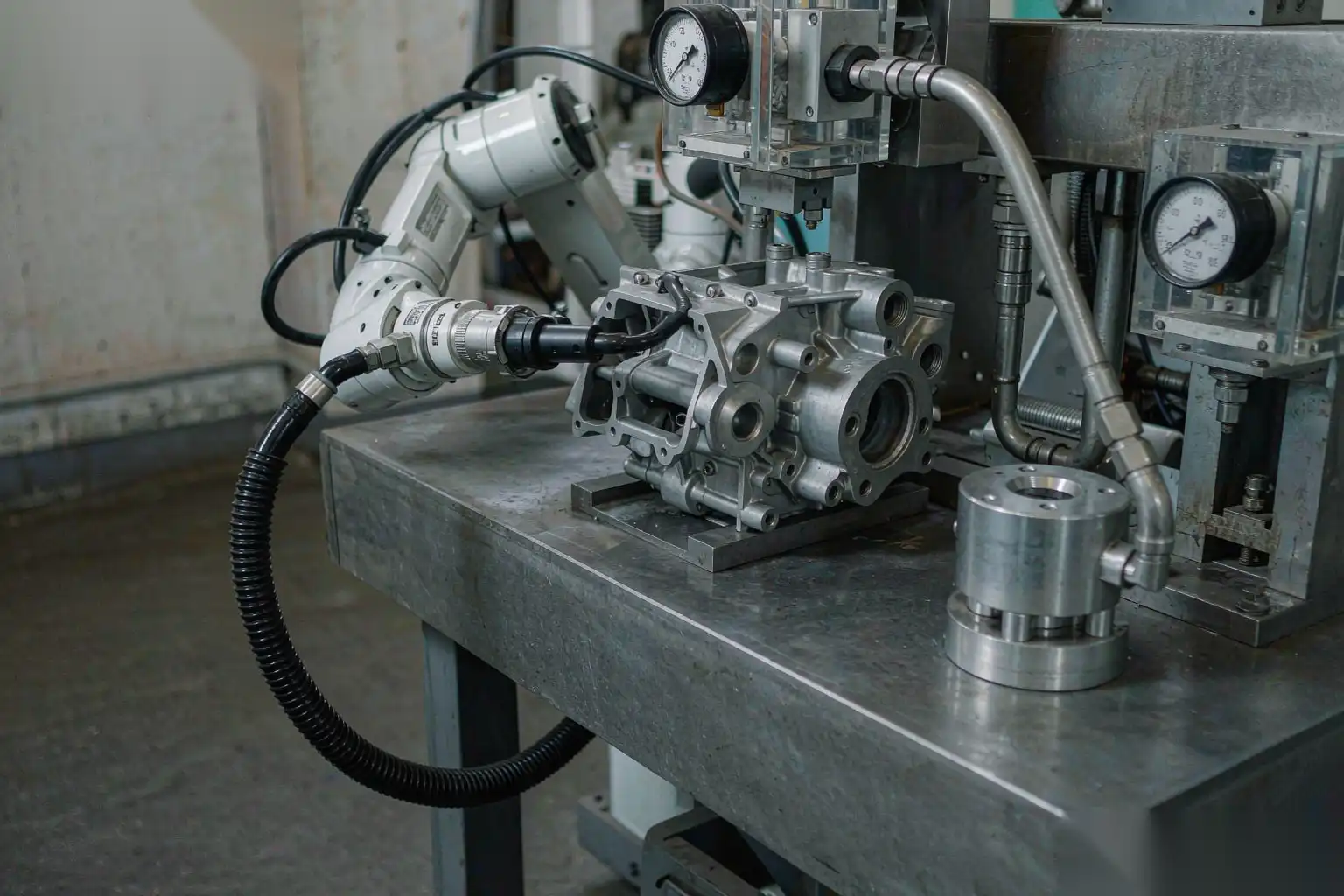
A balanced system is also what makes the downstream robotic finishing cell cheaper to run. When fill is even, the parting line is cleaner, flash is thinner, and the robotic deburring path can be taught once and repeated. When fill is unbalanced, operators compensate by widening gates, which throws more metal at the parting line and creates a thicker flash band that the how to deburr aluminum die castings automation cell then has to grind off at higher spindle load.
Runner Cross-Section, Flow Velocity and Pressure Drop

The runner is a pressure conduit. Its cross-sectional area sets the metal velocity for a given flow rate, and velocity sets the pressure drop through the Bernoulli and friction terms. For a trapezoidal or round runner of hydraulic diameter D_h, the mean velocity v_runner equals volumetric flow rate divided by area. The friction pressure loss over length L scales with v^2 and 1/D_h, so doubling the runner diameter cuts the velocity by a factor of four at fixed flow and cuts the friction loss by roughly a factor of sixteen.
We size runners with three constraints in mind:
- The runner must not freeze before the cavity fills. Aluminum in a thin runner loses heat to a cold die face fast; a runner under 6 mm equivalent diameter for A380 at 50 m/s will skin over on long parts.
- The runner velocity should be high enough to keep the metal moving as a coherent stream, but low enough that it does not atomize into the cavity. Between 5 and 10 m/s in the runner is a workable window for most aluminum jobs.
- The runner volume must be a small fraction of the shot so the biscuit and scrap stay manageable. A runner system that exceeds 35% of the total shot weight is a cost and thermal problem, not a safety margin.
The table below is a typical starting point for aluminum high-pressure die casting on a 400-900 ton machine. Treat it as a first estimate to be tuned by simulation, not as a finished design.
| Runner Ø or equiv. D_h (mm) | Runner velocity (m/s) | Shot weight carried (g) | Typical cavity fill time (ms) | Risk if oversized | Risk if undersized |
|---|---|---|---|---|---|
| 6 | 8-10 | 200-400 | 30-45 | Biscuit too large, more scrap | Freezing in runner |
| 8 | 6-9 | 400-900 | 25-40 | Slower thermal recovery | None at this size |
| 10 | 5-8 | 900-1800 | 20-35 | High scrap weight | None at this size |
| 12 | 4-7 | 1800-3200 | 18-32 | Cycle time from cooling | None at this size |
Pressure drop is not only theoretical. On a 660-ton machine with a 60 mm shot sleeve and a plunger velocity of 4 m/s, the available intensification pressure is around 70-90 MPa at the sleeve. Some of that is lost to friction in the sleeve, to acceleration of the shot mass, and to the gate restriction. If the gate is too small, plunger deceleration rises and the cavity never reaches the designed velocity; the part fills slowly and oxidizes. If the gate is too large, the metal enters at low velocity and produces a turbulent, cold, laminar-with-oxide fill. The gate is the control valve, and the runner is the supply line.
Gate Type Selection by Part Geometry
The gate is the point where velocity is converted into cavity fill. Gate type is selected by part geometry, wall thickness, cosmetic requirements and where the downstream robotic deburring automation cell will cut or grind the gate stub. The four families we use:
Fan gate
A fan gate spreads flow across a wide, thin entry, reducing local velocity while covering a long edge. It is the default for flat plates, appliance housings and large thin-wall panels where you want to avoid a single high-velocity jet drilling into the far wall. Fan gates produce a wide, low-profile gate scar that is easy to grind but requires a long trim or mill path.
Tab gate
A tab gate is a localized, thicker connection, often at a non-cosmetic edge or into a runner extension, that isolates the high-velocity jet from the part. The tab is then cropped. We use it where the part surface cannot tolerate gate-related flow lines, such as a visible faucet body shoulder. The cost is a separate cropping or milling operation and a small scrap tab.
Pinpoint gate
A pinpoint (or pin) gate is a small circular or rectangular restriction, common in multi-cavity and family tools, and in zinc. It gives precise fill control and a clean, small scar, but the high local velocity and small cross-section make it sensitive to freeze-off on aluminum and to abrasion. We reserve pinpoint gates for zinc and for small aluminum features fed off a robust runner.
Overflow (reserve) gate
An overflow is not a feed gate but a deliberate pocket placed at last-fill or cold-metal zones to catch the first, coldest, most oxidized metal and pull the air front ahead of it. Overflows are sized to absorb 5-15% of shot volume at the problem zones and are cropped with the runner. They are the cheapest insurance against cold shut and porosity at the end of fill.
Selection criteria we document on the tool drawing:
- Wall thickness under 1.5 mm: prefer fan or overflow-assisted edge gate to keep velocity controlled across a long thin path.
- Cosmetic face required: use tab gate into a scrap extension or a hidden edge, then mill.
- Symmetric multi-cavity: pinpoint or balanced fan with simulation-verified equal resistance.
- Deep drawers/cores: place overflows at the end of the longest flow path, not at the gate.
How Gate Location Sets Cold-Shut and Oxide Risk
Cold shut forms where two flow fronts meet with too little heat and velocity to weld. Gate location decides where those fronts meet. A single central gate on a long rectangular part sends two fronts toward the ends; if they meet at a far corner that is also the last-air zone, you get a cold shut wrapped around an air pocket. Moving the gate or adding an overflow at that corner changes the meeting point to a location where there is still heat and pressure.
Oxide risk is set by how much the metal is exposed to air during the fill. A high-velocity jet entering a deep pocket will splash and roll, folding the surface oxide skin into the part. Lowering gate velocity, widening the gate, or changing to a fan entry reduces splashing. We measure oxide-related defects by sectioning suspect parts and by pressure-decay leak testing on sealed features; a part that passes X-ray but fails leak test often has a localized oxide fold at a gate-imposed flow front.
Gate location also interacts with the die parting line. A gate placed across a moving slide or a core edge complicates the tool and produces a flash-prone seam. We keep gates on stable, flat parting surfaces wherever possible, and we document the gate scar as a defined feature with a maximum height and a defined trimming method so the finishing cell has a repeatable target.
Practical checks before tool steel is cut:
- Mark the predicted last-fill zone on the 3D model and confirm an overflow or vent sits there.
- Confirm the gate does not sit opposite a thin wall that will freeze before the front arrives.
- Confirm the gate scar is on a surface the finishing process can reach; a gate buried in a deep pocket cannot be trimmed by a standard robotic spindle without a custom tool.
- Run a fill simulation and read the “time to fill” and “temperature at fill” at the gate and at the last-fill zone; both should land inside the process window.
This is where a flow simulation step pays for itself: it shows the meeting of flow fronts and the temperature at each, turning gate location from guesswork into a tuned parameter.
Overflow Strategy: Sizing, Placement and Cropping
Overflows are engineered scrap. They do three jobs: absorb the first cold/oxidized metal, provide a path for trapped air to move ahead of the front, and locally heat the die so the end of fill stays liquid. The mistake is either omitting them (cheap tool, defective parts) or over-sizing them (wasted metal and longer cooling).
We size overflows against the defect they are meant to fix:
- For a cold-shut at a corner: a single overflow of 0.5-1.5 cc placed directly at the corner, connected by a short, wide channel so it fills last and pulls the cold metal in.
- For oxide at a flow-front meeting line: two overflows flanking the meeting line, sized to absorb the first 30-50% of metal arriving at that line.
- For air at a deep pocket: an overflow opening into the pocket’s last-fill point, sometimes vented itself.
Placement rules:
- Put overflows at last-fill zones, not near the gate.
- Connect overflows with a channel at least as thick as the gate so they actually fill.
- Keep overflows off cosmetic or machined surfaces; they are cropped and leave a scar.
- Total overflow volume is typically 5-15% of shot; above 20% review the whole gating balance because you are masking a balance problem with scrap.
Cropping matters for the finishing cell. Overflows cropped by a trim press leave a small nub; if that nub sits where a robot will deburr, plan the path so the spindle takes it in the same pass as the parting-line flash. If overflows are left on and only milled later, their location must be in the CNC or robotic program from the start.
Gating That Makes Robotic Deburring and Grinding Cheaper
The gating decision is made once, at tool design, but it is paid for or saved on every part across the tool life. A gating layout that respects the downstream finishing cell reduces total cost far more than shaving metal from the runner. We design gating and the robotic finishing path together, because the two are the same production system.
Design choices that reduce finishing cost:
- Keep the parting line straight and on a single plane so the flash band is uniform and the robotic path is a simple 2D-ish sweep. A wavy or stepped parting line forces a 3D-tracking spindle and slows cycle time.
- Locate gates and overflows on surfaces where a spindle or belt can reach without a custom tool. Avoid burying them in pockets deeper than the tool’s reach.
- Minimize total gate and overflow scar area; every square millimeter of scar is a grind or mill operation. A fan gate on a non-critical edge is cheaper to finish than a pinpoint cluster on a visible face.
- Hold flash thickness under 0.15 mm at the parting line. Above that, the robotic deburring cell needs higher spindle load and more belt wear, and the flatness control of the part can be affected by uneven trimming.
We quantify this at the quoting stage. A part with a 0.10 mm flash band and a single edge gate can be deburred in one robotic pass at a defined feed; the same part with a 0.30 mm flash band and three overflow stubs needs a second pass and a belt change per few hundred parts. Over a 200,000-part run that difference is thousands of finishing minutes and a measurable scrap-from-over-grind risk.
The DZ Smart Manufacturing engineering team designs gating and the post-casting robotic deburring, grinding and polishing cells as one system, so the gate location, flash band and finishing path are specified together from the first tool drawing. If you are quoting a new aluminum part, send us the 3D model and expected annual volume and we will return a gating proposal and a finishing-cell cycle estimate together.