Die Casting Die Steel Selection: Grades, Heat Treatment and Cost Per Shot
Die steel is the line item that looks like a small part of tooling cost and behaves like a large part of part cost. A die built from the wrong grade will still make good parts for the first 20,000 shots, and then it will start producing heat check lines on every cosmetic face, sticking on the deep ribs, and drift on the dimensions that your customer measures. By the time that shows up, the die is paid for and the programme is running, which is exactly the wrong moment to discover that a 12 percent increase in steel cost would have bought a 40 percent increase in die life.
This article is a practical selection guide: the grades that matter in aluminum die casting, the heat treatment windows that go with each, the hardness-versus-conductivity trade-off that drives most of the decision, surface treatments and when they earn their money, insert versus solid construction, and how all of it lands in cost per shot.
What Actually Kills a Die Casting Die
Before choosing steel, name the failure mode you are designing against, because there is no grade that optimizes all of them.
- Heat checking (thermal fatigue): the dominant failure mode. The die surface cycles from roughly 180 to 250 C up to 450 to 550 C and back, every shot, 40 to 60 times per hour. The surface layer yields in compression at peak temperature and goes into tension on cooling. Crack networks start at 3,000 to 15,000 shots on a hard die and become visible on the part long before the die is functionally dead.
- Erosion and washout: high velocity metal at the gate. Gate velocities in conventional HPDC run 30 to 60 m/s; at 50 m/s with a 2 mm gate thickness, the impinging stream removes material mechanically and by dissolution. Gate areas and the cores directly in the flow path are where you see it.
- Soldering and sticking: aluminum chemically attacks iron. Where the die surface is starved of lubricant or runs hot, aluminum welds to the steel and pulls material out on ejection. Deep ribs, thin cores and areas with poor spray coverage are the usual sites.
- Gross cracking: usually a heat treatment or a design problem rather than a grade problem — insufficient tempering, too high a hardness, sharp internal corners, or a core that cannot expand.
- Corrosion and rust in storage: underrated and expensive. A die put away wet develops rust pits that become heat check initiation sites in the next campaign.
Grades Compared
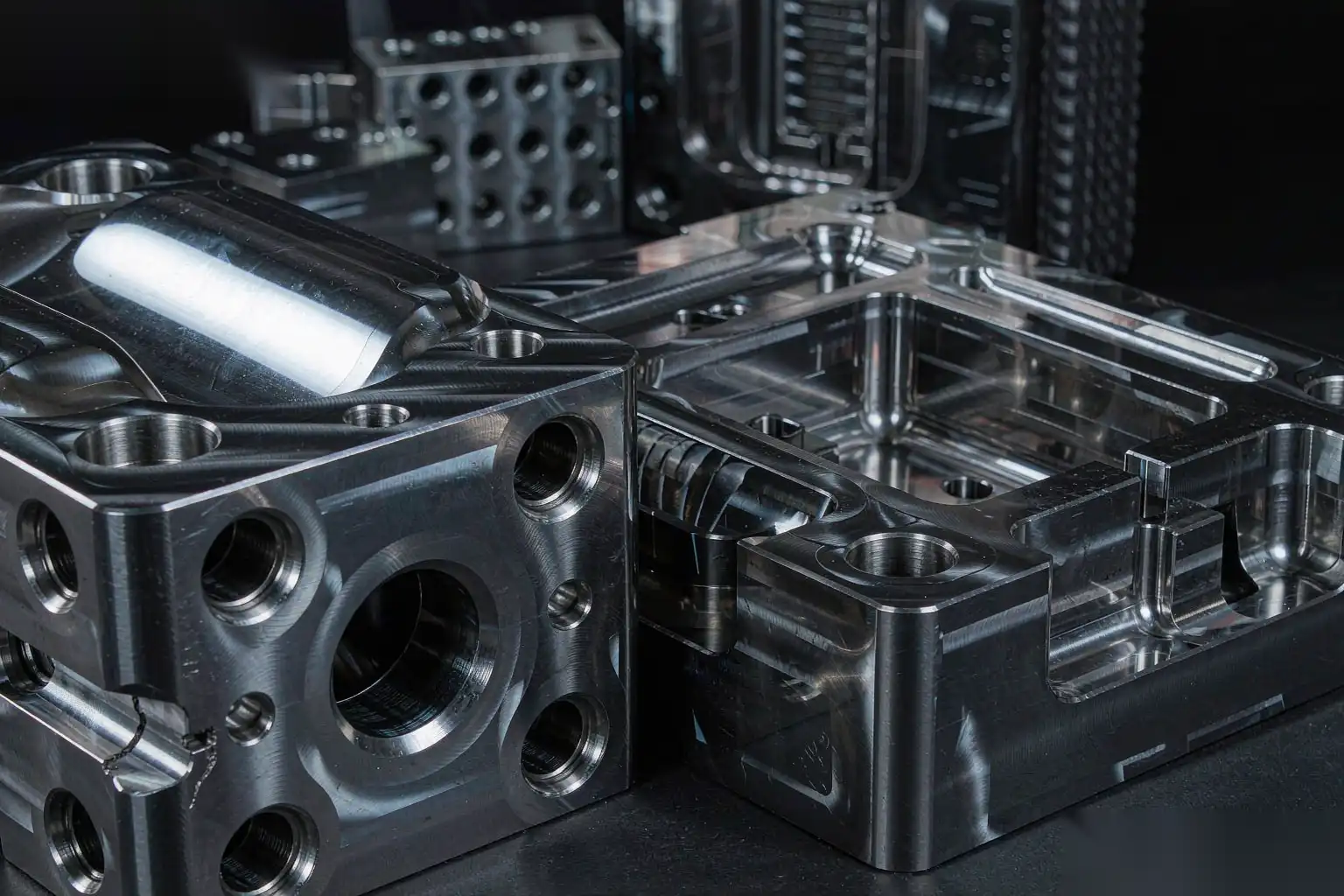
| Grade | Typical working hardness | Thermal conductivity at 400 C | Toughness | Heat check resistance | Relative material cost | Best application |
|---|---|---|---|---|---|---|
| H13 (standard ESR-free) | 44–48 HRC | 26–28 W/m·K | Good | Moderate | 1.0x | General purpose, low volume, large dies |
| H13 premium (ESR / VAR remelted) | 44–48 HRC | 27–29 W/m·K | Very good | Good | 1.6–2.0x | High volume, cosmetic parts, most production dies |
| H11 | 42–46 HRC | 28–30 W/m·K | Excellent | Moderate | 1.1–1.3x | Highly stressed cores, dies prone to gross cracking |
| H13 with higher Mo / V variant | 46–50 HRC | 25–27 W/m·K | Moderate | Very good | 1.8–2.2x | Long-run automotive structural parts |
| High conductivity Cu-alloyed tool steel | 38–42 HRC | 45–60 W/m·K | Moderate | Good | 3.0–4.5x | Thin-wall areas, hot spots, cores in 3C and thin-wall parts |
| Maraging (18Ni 300 / 350) | 50–54 HRC | 20–22 W/m·K | Excellent | Poor at high temp | 5.0–8.0x | Small inserts, slides, ejector pins, wear pads |
| Hot work steel for holder blocks (1.2343 / H11 mod) | 32–36 HRC | 28–30 W/m·K | Excellent | N/A | 0.8–1.0x | Die shoes, holder blocks, bolsters |
A few notes on reading that table. Hardness numbers are working hardness after tempering, not as-quenched. Conductivity figures vary by source and by temperature; the ranking is what matters. “Relative material cost” is steel purchase cost only — on a typical die, steel is 20 to 35 percent of the total die price, so doubling the steel cost raises the die price by roughly 20 to 30 percent, not 100 percent.
H13: The Default, With a Caveat
H13 (1.2344, AISI H13, approximately 0.38 C, 5.2 Cr, 1.3 Mo, 1.0 V) is the workhorse. It tempers to 44 to 48 HRC with good hot strength and adequate toughness. The caveat is that “H13” on a purchase order means very little without specifying the melting route. Conventional H13 has a banded structure and a population of non-metallic inclusions that are the initiation sites for heat check cracks and for gross fracture. Premium H13 produced by electroslag remelting (ESR) or vacuum arc remelting (VAR) has significantly lower inclusion content and a more homogeneous structure, and consistently delivers two to three times the heat check life in service.
Specify it explicitly: premium ESR H13, per North American Die Casting Association (NADCA) #207 or equivalent, with a certification showing the microstructure rating and the annealed hardness. On a die that will run 150,000 shots on a cosmetic part, this is the single highest-return specification in the whole package.
H11: When Toughness Governs
H11 (1.2343) has lower vanadium and slightly lower hot hardness than H13, but higher toughness. Use it where the risk is gross cracking rather than heat checking: large slender cores, dies with heavy section changes, and any die that has already fractured once in a location where you cannot change the design.
High Conductivity Alloys
These are the interesting ones for thin-wall work. The mechanism is straightforward: heat check cracking is driven by the temperature swing at the surface, and a steel that pulls heat away faster reduces the peak surface temperature for a given metal temperature and cycle. Typical copper-bearing hot work grades reach 45 to 60 W/m·K at 400 C versus 27 for H13.
The trade-off is that they are softer, typically 38 to 42 HRC, so they have less resistance to erosion at the gate and less resistance to mechanical damage. The correct application is not the whole die; it is a local insert:
- Thin-wall ribs and bosses that run hot and stick.
- Cores surrounded by metal on all sides that have no cooling line route.
- Areas where cycle time is limited by local solidification rather than by the thickest section.
We have seen 20 to 30 percent cycle time reductions from a single high-conductivity insert in a deep pocket, which on a 45-second cycle is worth more than the entire insert cost in a few weeks.
Maraging Steel for Small Inserts
18Ni maraging steel (300 or 350 grade) is aged at 480 to 500 C to reach 50 to 54 HRC with almost no distortion and exceptional toughness. It is used for small inserts, slides, ejector pins and wear plates, and for any small component where a heat check crack would be a tooling catastrophe. It is not a die cavity material for aluminum, because it loses strength above roughly 500 C and its conductivity is poor.
Heat Treatment: The Windows That Matter
Steel grade and heat treatment are one decision. A premium ESR H13 that is austenitized too hot or tempered too lightly will perform worse than a standard H13 treated properly.
- Annealing after rough machining: stress relieve at 650 to 680 C, hold 2 hours per 25 mm of section, furnace cool. Skipping this is a common cause of distortion in heat treat.
- Austenitizing: 1,020 to 1,050 C for H13. Going above 1,060 C grows the austenite grain size, which measurably reduces toughness and accelerates heat checking. Vacuum furnace with a 4 to 6 bar gas quench is standard; aim for a cooling rate through 850 to 500 C fast enough to avoid grain boundary carbide precipitation.
- Quench: do not quench to room temperature. Interrupted quench to 150 to 250 C, then equalize and temper immediately. Holding an untempered H13 block at room temperature is how dies crack before they are ever put in a machine.
- Tempering: minimum two tempers, usually three, at 560 to 620 C depending on target hardness. Each temper hold is a minimum of 2 hours at temperature, and the part must cool to below 60 C between tempers to complete the transformation of retained austenite.
| Application | Target hardness | Tempering range |
|---|---|---|
| Large die cavity, thick section | 42–45 HRC | 600–620 C |
| Standard production cavity | 45–47 HRC | 580–600 C |
| Small inserts, gate blocks, high wear | 47–50 HRC | 560–580 C |
| Deep slender cores, cracking risk | 40–44 HRC | 610–630 C |
| Holder blocks and bolsters | 32–36 HRC | 620–650 C |
| Ejector pins | 46–50 HRC (nitrided) | 560–580 C |
One rule worth stating plainly: going above 50 HRC on an H13 die cavity is almost always a mistake. The short-term benefit is better erosion resistance at the gate. The cost is a sharp drop in thermal fatigue resistance, and the die starts heat checking in the 10,000 to 20,000 shot range instead of the 60,000 to 100,000 range.
The Conductivity-Versus-Hardness Trade-Off
This is the core engineering decision, and it is worth stating in physical terms rather than as a rule of thumb.
Heat check life is governed by the strain range the surface experiences each cycle. That strain range is proportional to the temperature swing, the coefficient of thermal expansion, and the constraint, and inversely proportional to the yield strength at temperature. Hardness and hot yield strength resist crack initiation; conductivity reduces the temperature swing that drives the cycle in the first place.
- High hardness wins where the load is mechanical: gate impingement, sliding wear on cores and slides, ejection contact, and any location where the die is physically abraded.
- High conductivity wins where the load is thermal: thin sections, hot spots, and any location where the surface temperature peaks above roughly 520 C.
- Toughness wins where the load is structural: slender cores, sharp section transitions and dies that have cracked before.
Most dies are not homogeneous, and they should not be. The right answer is usually a 46 HRC ESR H13 cavity body with high-conductivity inserts in the two hot spots and a maraging or nitrided insert at the gate. That is more expensive to build and considerably cheaper to run.
Surface Treatments
| Treatment | Typical layer depth | Surface hardness | What it actually does | When it is worth it |
|---|---|---|---|---|
| Gas nitriding | 0.10–0.25 mm | 900–1,100 HV | Raises surface hardness, improves solder resistance, adds compressive stress | Cores and slides; can accelerate heat check if layer is too thick |
| Soft / controlled nitriding | 0.03–0.08 mm | 700–900 HV | Solder resistance with less brittleness | Aluminium die casting cavities at moderate volume |
| Plasma nitriding | 0.05–0.20 mm | 900–1,200 HV | Better control of compound layer, less white layer | Preferred over gas nitriding where available |
| PVD (CrN, TiAlN, AlCrN) | 2–5 µm | 2,000–3,500 HV | Very hard, low friction, reduces soldering and erosion | Gate inserts, small cores, high wear areas |
| Nitrocarburizing | 0.02–0.06 mm | 600–800 HV | Mild solder resistance, cheap | Low volume, non-cosmetic |
| Duplex (nitride + PVD) | — | — | PVD supported by a nitride case; best wear result | Gate blocks on long-run dies |
Practical cautions, learned the hard way:
- A nitrided layer thicker than roughly 0.25 mm on a cavity face becomes a heat check accelerator. The compound layer is brittle and it cracks, and the cracks propagate straight into the base steel. Specify a thin, controlled compound layer and ask for the white layer thickness on the certification.
- Nitriding raises the effective surface hardness but does not change the bulk. It will not rescue a die that is too soft in the core.
- PVD coatings fail at sharp edges and at high thermal cycling amplitude. Do not coat a sharp corner and expect it to last; put a 0.3 to 0.5 mm radius on first.
- Surface treatments must be reapplied. A nitrided cavity that has been dressed twice to remove heat check has had its case removed. Budget for re-treatment at each major maintenance, or accept that the treatment only benefits the first campaign.
- Rust is the enemy during storage. After any water-based cleaning, dry the die, apply a rust preventive, and store it with the cooling channels blown out.
Surface treatment choice interacts with the part’s cosmetic requirement. A die that heat checks produces parts with a replicating crack pattern on the class A face, and no amount of downstream polishing removes it without changing the part geometry. If your part is cosmetic, the aluminum die casting mold design guide considerations of gate location and thermal balance should be settled before you start choosing a coating.
Insert Versus Solid Construction
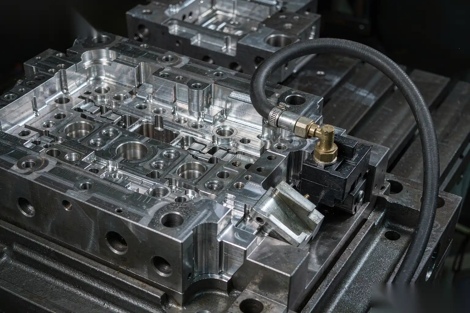
Solid cavities are simpler, stiffer and cheaper to build for small dies. Inserts cost more in steel, machining and fitting, but they give you four things:
- Localized material selection. High-conductivity steel only where it is needed, wear-resistant steel only at the gate, tough steel only on the slender core.
- Replaceability. A heat-checked insert is replaced in a day; a heat-checked solid cavity means a new die block and weeks of lead time.
- Maintenance access. Inserts can be removed, dressed, re-nitrided and reinstalled without taking the die out of the frame.
- Venting. Insert parting lines are natural vent paths when designed correctly, which reduces the porosity you would otherwise fight with vacuum.
The cost of inserts is the fit. Every insert adds a fit surface that must be ground, and every gap is a flash site. We recommend inserts when the die is above roughly 400 x 400 mm, when the expected life exceeds 80,000 shots, or when there is a known wear or hot-spot location. Below that, solid is usually right.
How Steel Choice Lands in Cost Per Shot
Here is the calculation that should drive the decision, applied to a 62,000-shot-per-year programme on a mid-size cosmetic housing.
| Scenario | Standard H13, 47 HRC | Premium ESR H13, 46 HRC | ESR H13 + high-cond. inserts, nitrided |
|---|---|---|---|
| Die build cost (USD) | 54,000 | 68,000 | 79,000 |
| Shots to first heat check on cosmetic face | 28,000 | 65,000 | 95,000 |
| Major refurbishments over 300,000 shots | 5 | 2 | 1 |
| Refurbish cost each (USD) | 9,500 | 9,500 | 11,000 |
| Cosmetic scrap rate, avg | 6.5% | 3.2% | 2.4% |
| Scrap cost over 300,000 shots at 22 USD (USD) | 429,000 | 211,200 | 158,400 |
| Total tooling plus refurbish (USD) | 101,500 | 87,000 | 90,000 |
| Total cost of quality plus tooling (USD) | 530,500 | 298,200 | 248,400 |
The premium die costs 14,000 USD more to build and saves 232,000 USD over 300,000 shots, and the dominant term is not tooling — it is cosmetic scrap caused by heat check transfer to the class A face. That is the number most buyers never calculate, because the scrap shows up in the finishing department and the tooling decision was made in the purchasing department.
A second way to express it: cost per shot for tooling only, over 300,000 shots, is 0.34 USD for the standard die and 0.30 USD for the premium die. Add the scrap difference and the real cost per shot is 1.77 USD versus 0.99 USD.
What to Write in the Die Specification
Put these lines in the purchase order, not in an email:
- Grade and melting route: premium ESR H13 to NADCA #207 or equivalent, with microstructure certification.
- Target hardness range and the number of tempers.
- Austenitizing temperature ceiling, and a prohibition on single-temper cycles.
- Nitriding specification including compound (white) layer thickness, or an explicit “no nitriding on cavity faces.”
- Insert material and hardness for each identified hot spot or wear location.
- Weld repair procedure for the die, including preheat and post-weld temper. A die welded without preheat and re-tempered afterwards is a die that cracks at the repair.
- Maintenance interval and the acceptance criterion for heat check depth at which the cavity will be dressed (0.15 mm is a common threshold on cosmetic dies).
If you also specify the inspection interval and the criterion for end of life before the die is built, you convert tooling from a capital argument into a maintenance plan.
Where the Finishing Line Sees the Difference
The downstream signature of a die steel problem is very specific. It is a cosmetic defect that appears gradually, gets worse through the shift as the die heats, and improves after the die is cooled or dressed. Flow lines and heat check transfer on the class A face, sticking marks on deep ribs, and parting line witness that grows with shot count are all die surface conditions, not polishing conditions.
This matters because the usual reaction is to add polishing. That works for a while, and then it does not, and by then the polishing step has absorbed the cost of a tooling decision. The better response is to detect the drift early, which is one argument for automated finishing: a force-controlled robotic cell removes a constant amount of material by programmed path and pressure, so when the incoming casting surface changes, the finished result changes in a measurable way rather than being absorbed by an operator who unconsciously presses harder.
If you want to understand how the cosmetic requirement propagates from the die to the finishing cell, the die casting surface finish standards discussion of limit samples and roughness targets is the natural companion to this article, and the aluminum die casting tooling guide covers the tooling cost structure in more depth.
DZ Machinery designs robotic deburring, grinding and polishing cells for die cast and faucet hardware, and we specify the finishing process against the actual incoming casting condition rather than a nominal drawing. If you are planning a new cosmetic programme and want the die life, scrap rate and finishing cost considered together, send us the part drawings and your annual volume, and our engineering team will work through the cost-per-shot model with you.