Die Casting Die Cooling System Design: Cycle Time and Distortion
The cooling system inside a die casting die is the single biggest lever on two numbers that decide whether a job is profitable: cycle time and dimensional stability. A die that removes heat evenly and quickly lets you shorten the solidification window, raise cavitation rate, and hold flatness and bore position across a run. A poorly balanced cooling layout does the opposite: long cycles, hot spots that warp the part, and thermal fatigue that cracks the steel. This article covers how we design die cooling at DZ Smart Manufacturing, from line placement to flow control and how process data closes the loop.
Why cooling controls cycle time and dimensional stability
Every shot starts by dumping several hundred degrees of superheat into the die. The metal must lose that heat before it is strong enough to eject without distortion, and the die steel must recover before the next shot or it runs hotter every cycle until it stabilizes at an unacceptable temperature. Cooling is what sets both clocks.
Cycle time is gated by solidification. For a typical aluminum wall section of 3 mm, solidification takes a few seconds; a thick boss of 10 mm can take several times longer. If the die pulls heat out faster at that boss, the whole cycle shortens. On a 60-second aluminum cycle, cutting solidification by 20 percent can drop the cycle near 50 seconds, which is a 20 percent gain in cavitation rate on the same machine, a direct throughput and cost win.
Dimensional stability comes from thermal balance. A die that is hot on one side and cool on the other expands unevenly, so the cavity geometry shifts between the first and the thousandth shot, and the part warps toward the hot side. The parting line, the core, and the ejector area all move with temperature. Holding the die within a tight temperature band, often plus or minus 10 to 20 degrees C around a setpoint near 180 to 220 degrees C for aluminum, keeps the cavity where it was cut.
Cooling also protects the steel. Thermal cycling is what grows heat-check cracks; a stable, moderate die temperature with smooth flow delays that fatigue and extends tool life, which we detail in our die casting tooling maintenance and life guide.
Cooling-line placement versus heat hotspots

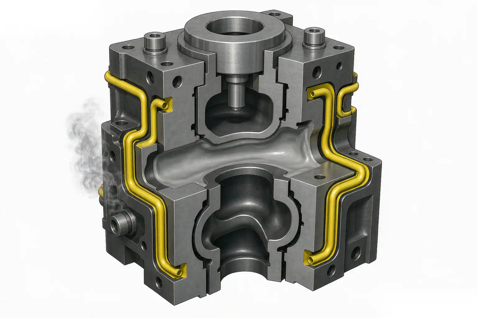
Heat is not uniform in a die. It concentrates where metal enters (the gate and runner), where sections are thick (bosses, gearbox walls), and where metal pools (the last place to fill). Cooling lines must be placed against those hotspots, not spread evenly for convenience.
We map heat load before drilling. The gate area can run 50 to 100 degrees C hotter than the far cavity, so it gets the densest cooling lines, often at 15 to 25 mm from the cavity surface with 30 to 50 mm spacing between lines. Thick sections get a line or a bubbler directly behind them. Thin, cosmetic faces get little or no cooling so they do not chill too fast and cause cold flow or sink.
Distance from the cavity is the key geometric rule. Too close and the surface freezes so fast you get cold shuts, surface veins, or local hardness; too far and the line does nothing. For aluminum we hold cooling lines roughly 1.5 to 2.5 times the line diameter from the cavity, typically 12 to 30 mm depending on section. The line must also clear ejector pins, water burs, and core steel so it does not weaken the structure.
The table below shows a typical placement logic for an aluminum hardware or enclosings die.
| Region | Heat load | Line distance from cavity | Spacing | Target temp |
|---|---|---|---|---|
| Gate and runner | High | 15-20 mm | 30 mm | 190-210 C |
| Thick boss | High | 18-25 mm | Local bubbler | 180-200 C |
| Thin cosmetic wall | Low | 25-35 mm or none | Wide | 200-220 C |
| Core pin | Medium | Around pin | Bubbler | 190-205 C |
| Parting line edge | Medium | 20-30 mm | 40 mm | 195-210 C |
Baffles and bubblers for deep cores
Many die cast parts, lock cylinders, sensor housings, and enclosures among them, have deep cores that a straight line cannot reach. A line drilled from the parting face runs out of steel before it gets to the tip of a 60 mm core, so the tip stays hot, the core bends under thermal growth, and the bore dimension drifts. Baffles and bubblers solve this.
A bubbler is a small tube placed inside a drilled hole; water flows down the tube, hits the bottom, and returns up the annulus, sweeping the full depth of the core with fresh coolant. This is the standard way to cool a long core pin. We size the tube so the annular gap gives turbulent flow without excessive pressure drop, and we seal the bottom so all flow returns.
A baffle is a plate or tube that splits a line into two paths inside a pocket, forcing water to one side and back the other. Baffles are used where a core is wide but not deep enough to need a bubbler, or where a line must cool a broad area from one inlet. Both methods exist to put coolant where a straight drill cannot reach.
For very deep or thin cores, we sometimes use a core-cooling insert with its own feed, or a heat-pipe style solution on demanding tools. The aim is always the same: the tip of the core must be within a few degrees of the base, or the part dimension at that feature will not hold.
Turbulent versus laminar flow and flow rate
Flow regime decides how well heat actually transfers. Laminar flow slides water along the wall in smooth layers; only the outer layer touches the steel and heat transfer is weak. Turbulent flow mixes the water so every parcel reaches the wall, and the heat-transfer coefficient jumps several times.
We design for turbulent flow in every cooling line. The rule of thumb is a Reynolds number above 4,000, which for water in a 10 mm line at casting temperatures means a velocity around 1.5 to 2.5 m per second, or a flow near 1 to 2 liters per minute per line depending on diameter. Below that, you are wasting drilled steel.
Flow rate is balanced across the die, not maximized at one line. If the gate line gets 4 liters per minute and a far line gets 0.5, the die is still unbalanced. We tune restrictors or use separate zones so each line carries the flow its heat load needs. A flow meter or pressure differential sensor at the manifold tells us the line is actually moving water, because a blocked or air-locked line is a silent killer of dimensional stability.
Water quality matters too. Scale or biological growth narrows lines and drops turbulence, so we spec treated water with corrosion inhibitor and a filter, and we monitor flow drift as a maintenance trigger.
Thermal balance to reduce warpage
Warpage is the part bowing, twisting, or shifting a feature because one side cooled faster than the other. The fix is thermal balance, meaning the die temperature field is symmetric and stable so the part shrinks evenly.
We start by balancing line density on both cavity and core halves. A part that warps toward the cavity side usually means the core is hotter; we add core cooling or reduce cavity cooling. A part that bows the other way gets the opposite treatment. This is iterative and we confirm with a flatness and profile check, the methods for which are in our die cast warpage and flatness control guide.
Ejector and sliding areas are warpage hotspots. The ejector pins sit in steel that is hard to cool, so they run hot and grow, which can seize or mark the part. We route cooling close to the ejector zone and sometimes give pins their own light cooling path so they stay in dimension.
Thermal balance also means controlling the die temperature setpoint against the melt and the cycle. If the machine speeds up, more heat enters per minute and the die climbs unless cooling flow rises to match. We link cooling flow to cycle rate so the die temperature band holds as production ramps.
A practical check we use is to measure part flatness and feature position on the first articles from a cold die and again after the die has reached steady state, typically after 50 to 100 shots. If the bore or a flat face moves more than the tolerance band between those two points, the die is not thermally balanced and the cooling map needs revision before the job is released. This cold-to-hot shift is the number that separates a die that holds dimension from one that drifts all shift.
Cooling and ejector-pin life
Ejector pins live a hard life: they slide, they carry part weight off the core, and they sit in the hottest, hardest-to-cool steel. Cooling design directly affects how long they last.
A pin running hot grows and galls against its sleeve; a pin running with a steep local gradient cracks at the shoulder. We keep the pin zone within the same temperature band as the rest of the core and avoid a hard cooling line right at the pin shoulder that would create a thermal shock line. Where pins must be near a cooling line, we keep a safe steel bridge, typically 8 to 12 mm, so the line does not weaken the pin bore.
Lubrication and venting at the pin also tie back to temperature. A cooler, stable pin zone keeps the release agent effective longer and reduces build-up that eventually freezes the pin. When pins start to stick, the first check is whether the local cooling drifted, because a hot pin zone is a common root cause.
Tool life tracking tells us when cooling design is wrong. If pins or a cavity area fail early while the rest of the die is fine, the cooling map around that feature is the suspect, not the steel grade.
Measuring and optimizing with process data
Cooling design is not finished when the steel is cut; it is validated and tuned with data on the floor. Our approach uses the process monitoring described in our die casting process data monitoring guide.
We instrument the die with temperature sensors at the gate, the core tip, and a reference cool zone, logging every shot. The trend shows whether the die reaches a stable band or keeps climbing. A die that never stabilizes within the first 50 to 100 shots signals a cooling shortfall at a hotspot.
Flow and pressure at each manifold zone are logged so a drop in one line is caught before it distorts parts. We set alarm limits, for example flow below 80 percent of set, and the cell flags the condition instead of shipping bad parts.
Cycle time and scrap are then correlated. If warpage scrap rises as the die temperature creeps up over a shift, the cooling flow or setpoint is the lever, and we adjust the zone flow or the machine rate. The data closes the loop: design intent, actual temperature, and part quality in one view.
Optimization is ongoing. As the die wears or the alloy batch shifts, the cooling setpoint may need a small move. We keep the tuning in the process recipe so the next shift runs the same proven window, and we feed tool-life and scrap data back into the next die’s cooling layout.
Die cooling design is where cycle time, warpage, and tool life are won or lost. Place lines against the real heat load, reach the cores you cannot with straight drills using bubblers and baffles, force turbulent flow with balanced rate, and hold the die in a tight temperature band verified by sensor data. DZ Machinery supports die casters with process monitoring and the downstream robotic finishing cells that turn thermally stable, dimensionally consistent castings into finished parts; if you want to review a die cooling layout or a production data plan for your tool, our engineering team can work through it with your drawings.