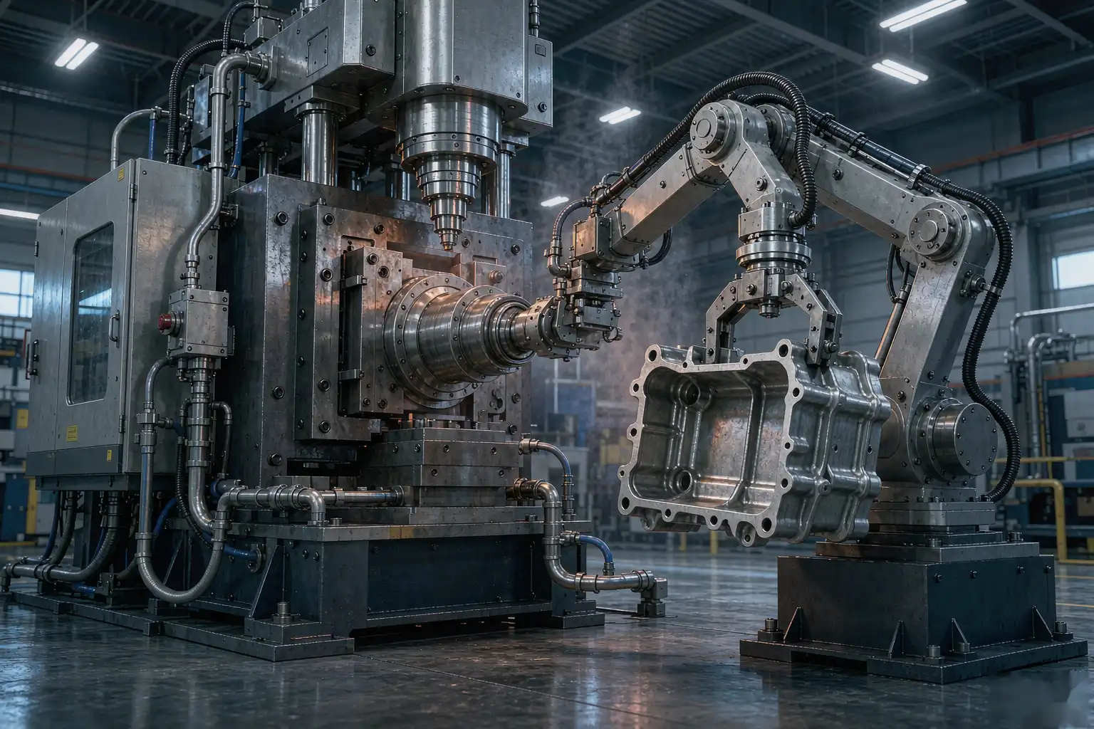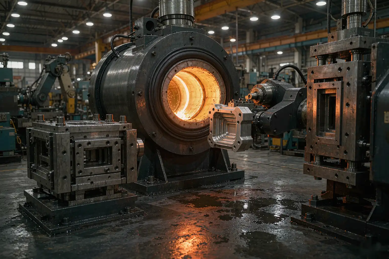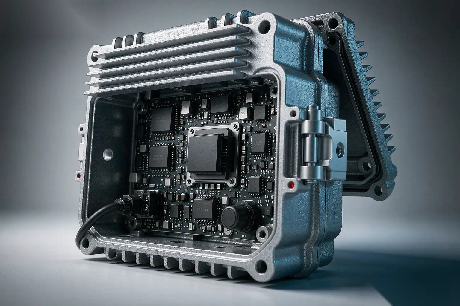
Die Cast Aluminum Enclosure Design: From Requirements to Production
Why Die Cast Aluminum Is the Default for Enclosures
For electronic enclosures, industrial equipment housings, and outdoor product housings, die cast aluminum is often the right answer:
- Structural rigidity — withstands impact, vibration, and rough handling
- EMI/RFI shielding — natural metal enclosure blocks electromagnetic interference
- Heat dissipation — acts as a heat sink for internal electronics
- IP rating — provides ingress protection when properly sealed
- Premium appearance — looks and feels high-quality
- Recyclable — sustainable end-of-life option
The trade-off vs plastic enclosures is weight and cost. Die cast aluminum enclosures typically cost 30-50% more than plastic and weigh 2-3x as much. For premium products, industrial applications, or any product where the enclosure is part of the value proposition, the trade-off is worth it.
Structural Design Rules
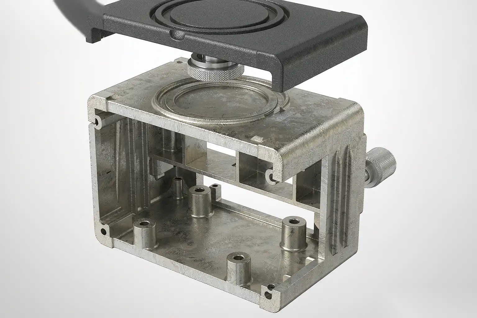
Wall Thickness
The single most important design parameter:
- Minimum wall: 1.5 mm for A380 (achievable in HPDC)
- Recommended minimum: 2.0 mm for robust production
- Maximum single wall: 4.0 mm (thicker walls cause shrinkage porosity)
- Wall thickness variation: ±0.5 mm within any single wall, ±1.0 mm between adjacent sections
Non-uniform wall thickness is the #1 cause of die casting defects. Use ribs, gussets, or cores to add stiffness without thick walls.
Ribs and Gussets
For added stiffness without weight:
- Rib thickness: 60-80% of the adjacent wall thickness (thinner than the wall to avoid hot spots)
- Rib height: typically 3-5x the wall thickness
- Rib spacing: 4-6x the wall thickness for maximum stiffness
- Draft angle: 1-3° on all rib surfaces, same as walls
Bosses and Mounting Features
For internal component mounting:
- Boss diameter: typically 2-3x the screw diameter
- Boss wall thickness: 0.6-0.8x the nominal wall
- Boss spacing: minimum 2x the boss diameter from edges or other bosses
- Undercut for self-tapping screws: optional, requires slide in the die
Fillets and Radii
- Internal fillets: R0.5 minimum, R1.0 preferred
- External corners: small radius (R0.5-1.0) for appearance, sharp for technical surfaces
- Rib-to-wall junctions: R0.5-1.0 fillet to reduce stress concentration
Thermal Design
For enclosures with internal heat sources (electronics, drivers, batteries), the enclosure can act as a heat sink.
Heat Transfer Paths
- Conduction from internal heat source through the enclosure wall
- Convection from the external surface to ambient air
- Radiation from the external surface, especially if black anodized
Heat Sink Integration
For high-power applications, integrate heat sink fins directly into the enclosure:
- Fin height: 15-40 mm typical for natural convection
- Fin thickness: 1.5-3.0 mm for castability
- Fin spacing: 8-12 mm for natural convection
- Draft on fins: 1-3° (mandatory for castability)
- Material: A380 or A384 (better thermal conductivity than A390)
Thermal Interface Material
Between the heat source and the enclosure:
- Thermal pads: pre-cut, easy to apply, 0.5-5.0 W/m·K conductivity
- Thermal paste: higher conductivity (1-10 W/m·K), messier to apply
- Thermal epoxy: permanent bonding, high conductivity
- Gap pads: compressible, fill uneven gaps, 1-15 W/m·K
Choose based on the assembly process and the thermal resistance requirement.
Electromagnetic Compatibility (EMC)
Aluminum enclosures provide natural EMC shielding. To make it effective:
Conductive Continuity
- Mating surfaces must be conductive — no paint, anodizing, or other non-conductive coating on the mating surfaces
- Conductive gaskets (silver-filled silicone, beryllium copper finger stock) at cover seams
- Grounding of all metal parts to a common ground point
- Cable entry through shielded connectors with conductive grommets
Apertures and Penetrations
Apertures in the enclosure leak EMI. To minimize leakage:
- Slot aspect ratio (length/width) — keep below 3:1 for best shielding
- Maximum aperture size — keep below λ/20 of the highest frequency to be shielded (e.g., 6 mm at 2.5 GHz)
- Honeycomb vent panels for required airflow — much better than perforated sheet
- Conductive mesh over any large openings
Surface Treatment and EMC
Anodizing (especially Type II and Type III) creates a non-conductive aluminum oxide layer. For EMC:
- Mask the mating surfaces before anodizing
- Use chem film (chromate conversion) instead of anodizing on mating surfaces
- Use conductive gaskets to bridge non-conductive coatings
Sealing and IP Rating
For enclosures requiring IP rating (dust and water protection):
IP Rating Requirements
| Rating | Dust | Water |
|---|---|---|
| IP54 | dust-protected | splash from any direction |
| IP65 | dust-tight | water jets from any direction |
| IP66 | dust-tight | powerful water jets |
| IP67 | dust-tight | immersion to 1m for 30 min |
| IP68 | dust-tight | continuous immersion (specified depth) |
Sealing Design
- Gasket groove — machined or cast into one mating surface
- Gasket compression — 20-30% of the original gasket thickness
- Gasket material — silicone for high temperature, EPDM for weather, fluorocarbon for chemical resistance
- Drainage — drain path for any condensation or water ingress
- Cable entry — sealed cable glands, IP-rated connectors
Common Sealing Mistakes
- No compression stop — over-compression of the gasket causes failure
- Insufficient groove depth — gasket extrudes under compression
- No drain — water pools inside, leading to corrosion
- Wrong gasket material — chemical attack, UV degradation, temperature failure
- Painted sealing surfaces — paint prevents proper gasket contact
Surface Finish
The enclosure finish affects appearance, durability, and function:
- As-cast + bead blast: industrial look, low cost
- Anodizing (Type II): premium look, color options, scratch resistant
- Powder coating: wide color range, UV resistant, hides surface defects
- Wet paint: highest color matching, premium appearance, higher cost
- Polished + clear coat: premium consumer look, requires hand finishing
For multi-color or selective finishing, mask critical surfaces during the main finish application.
Manufacturability Considerations
The enclosure must be both a good product AND a manufacturable part.
DFM (Design for Manufacturability) Review
Before tooling, the die caster should review:
- Wall thickness uniformity — flag any non-uniform sections
- Draft angles — confirm all draw surfaces have proper draft
- Parting line — propose a parting line that minimizes flash visibility
- Gate location — propose gate location for clean fill
- Slide requirements — confirm any side-action features
- Ejector pin locations — propose ejector pin layout
- Die steel selection — based on production volume
- Cooling channel layout — based on thermal simulation
A good DFM review takes 5-7 days and saves months of tooling rework.
Tolerance Specification
For an enclosure, typical tolerances:
- Overall dimensions: ±0.20 mm per 100 mm
- Mounting hole locations: ±0.10 mm
- Mating surface flatness: 0.20 mm per 100 mm
- Wall thickness: ±0.20 mm
- Surface roughness on cosmetic surfaces: Ra 1.6 µm (after finishing)
Tighter tolerances should be specified only on features that mate with other parts or affect assembly.
Tooling Considerations
- Tooling cost: $20,000-80,000 for a typical enclosure die
- Tooling lead time: 6-10 weeks
- Die life: 100,000-300,000 shots for H13 tool steel
- Multi-cavity options: 2-cavity or 4-cavity dies for higher production rate (higher tooling cost)
Common Design Mistakes
In our experience, the most common enclosure design errors:
- Non-uniform wall thickness — the most common cause of die casting defects
- Insufficient draft — parts drag, scuff, or break during ejection
- Underestimating heat sink integration — fins designed without considering castability
- No EMC plan — painted mating surfaces kill shielding effectiveness
- Ignoring the finishing process — design assumes as-cast finish, customer expects painted finish
- Tight tolerances on cosmetic features — drives cost without functional benefit
- No DFM review — design frozen before die caster input
- Wrong alloy for the application — A380 specified for pressure-tight or decorative parts
These are all preventable with a thorough DFM review before tooling.
Prototyping Paths Before You Commit to a Die
A die is a six-figure, six-week commitment, and the single most expensive enclosure mistake is cutting steel on an unproven design. Three prototyping paths de-risk it, in rising order of fidelity. Machined prototypes from billet deliver true material properties and real thermal behavior within two to three weeks — the right choice for EMC pre-scans, thermal testing, and fit checks, though machining cannot reproduce casting-specific artifacts like parting-line witness or as-cast surface texture. 3D-printed metal parts close that gap partially at lower cost, and work well for mechanical fit and cosmetic mockups, but their thermal and mechanical data should be labeled indicative rather than qualifying. A soft or prototype die — aluminum or P20 steel, good for a few thousand shots — is the highest-fidelity path, producing true die cast parts with real porosity behavior and real finishing response, and it costs a fraction of a production die.
The rule of thumb: anything the enclosure must prove electronically or thermally, prove on machined metal; anything it must prove about castability and finishing, prove on a soft die or skip the proof and accept the schedule risk.
DZ Machinery regularly supports customers at this exact fork. Send us a machined prototype and the production drawing, and we will run the finishing trial that predicts how the die cast version will deburr, grind, and polish — cycle time, abrasive selection, and the surface finish you should expect at rate. It is the cheapest possible look at the last third of your cost structure before the die is ordered.
FAQ About Die Cast Aluminum Enclosure Design
What is the minimum wall thickness for a die cast aluminum enclosure?
1.5 mm is the absolute minimum for A380 in HPDC. For robust production, 2.0 mm is recommended. Below 1.5 mm, the die casting process becomes unreliable.
How do I achieve IP67 on a die cast aluminum enclosure?
IP67 requires: machined gasket grooves, high-quality silicone gaskets, sealed cable entries, drain paths, and pressure-equalizing vents (ePTFE type). The die cast surface provides a good sealing substrate, but precision machining of the gasket groove is usually required.
Can I integrate a heat sink into the die cast enclosure?
Yes — this is the standard approach for high-power electronics enclosures. The fins are cast directly into the enclosure wall. Design with 1.5-3.0 mm fin thickness, 8-12 mm fin spacing, and 1-3° draft on all fin surfaces. Specify A380 or A384 for best thermal conductivity.
How long does tooling take for a die cast aluminum enclosure?
Plan 6-10 weeks for the die: 1-2 weeks for DFM and tool design, 4-6 weeks for die fabrication, 1-2 weeks for sampling. Add 2-3 weeks for finishing setup if finishing is at a different facility.
A Realistic Design Process
A typical die cast aluminum enclosure project takes 12-20 weeks from concept to first production:
- Weeks 1-3: concept design, thermal analysis, structural analysis
- Weeks 3-5: detailed design, DFM review with die caster
- Weeks 5-11: die fabrication
- Weeks 11-13: sampling (T0, T1, T2)
- Weeks 13-16: PPAP, finishing validation, EMC testing
- Weeks 16-20: pre-production runs, quality system audits
- Week 20+: production
Investing more time in the first 5 weeks (design + DFM) saves months later in the project.
At DZ Smart Manufacturing, our robotic finishing cells handle the surface preparation and finishing of die cast aluminum enclosures across consumer, industrial, and outdoor applications. If you are designing a new die cast aluminum enclosure and want feedback on the finishing scope, EMC compatibility, or thermal management, our engineering team can review your design and suggest improvements that will save you time and money in tooling and production.