Brass faucet castings leave the foundry with parting line flash, gate vestiges, and core shift burrs that must be removed before polishing and plating. In a faucet production line, deburring sits between casting and polishing—and it is often the bottleneck. Inconsistent deburring leads to uneven plating adhesion, leaking assemblies, and costly customer returns.
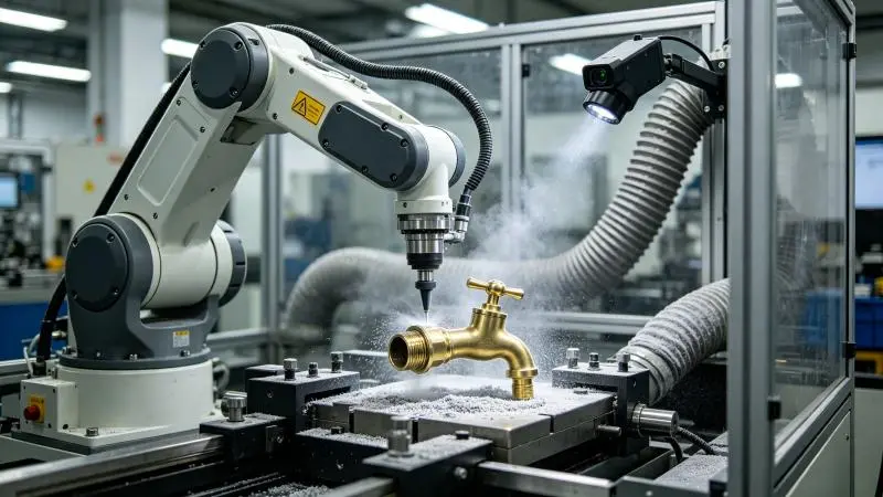
An automatic deburring machine designed for brass faucets changes this. Instead of relying on skilled operators with hand files and grinding wheels, a robotic system removes burrs with repeatable precision on every part. This guide walks through the complete process—from part loading to quality verification—so you understand exactly what automated deburring looks like in a brass faucet production environment.
Understanding Brass Faucet Casting Burrs
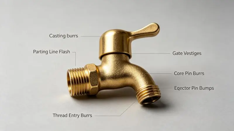
Before setting up the deburring process, it helps to know what you are removing. Brass faucet castings typically have five types of burrs:
Parting line flash. A thin fin of metal along the mold split line that runs the full length of the faucet body. This is the most common burr and the largest surface area to deburr.
Gate vestiges. The raised remnants where molten brass entered the die cavity. These are typically located on the underside or non-visible surface of the casting and range from 1–5 mm in height.
Core pin burrs. Small circular raised edges around waterway openings created by core pins in the die. These must be removed cleanly to ensure proper sealing with O-rings and gaskets in the final assembly.
Ejector pin marks. Small raised bumps (1–3 mm diameter) where ejector pins pushed the casting out of the die. Usually located on non-visible surfaces.
Thread protection burrs. Small burrs at the entry and exit of threaded sections (inlet/outlet connections). These must be removed without damaging the threads themselves.
Each burr type requires a specific tooling approach, which the automatic deburring machine handles through programmed tool changes.
Step 1: Part Loading and Fixturing
The process begins with securing the brass faucet casting in the deburring cell. Most automatic deburring machines use one of two loading methods:
Manual loading. An operator places the casting onto a fixture on a rotary index table. The table rotates the part into the robot’s working envelope. This is common for medium-volume production (500–2,000 parts/day) where mixed models run on the same cell.
Automated loading. A conveyor or gantry system delivers castings from the upstream operation directly into the deburring cell. A vision system identifies the part model and confirms proper positioning. This is used in high-volume lines (2,000+ parts/day).
The fixture itself is critical. For brass faucets, fixtures are typically machined from aluminum or nylon to match the casting contour. Pneumatic clamps secure the part at three or four points, ensuring it does not shift during deburring. The fixture design must leave all deburring surfaces exposed—including internal waterway openings—so the robot can reach every edge that needs work.
Step 2: Tool Selection and Setup
For brass faucet deburring, the automatic machine typically uses three to five different tools in a single cycle, swapped automatically through a tool changer:
Tool 1—Carbide burr for parting line flash. A cross-cut tungsten carbide burr, 10–16 mm diameter, running at 10,000–14,000 RPM. This tool follows the main parting line contour around the faucet body. Force control is set to 8–15 N—enough to shear the flash without cutting into the casting body.
Tool 2—Small carbide burr for gate vestiges. A 6–8 mm diameter ball-end carbide burr for spot-removing gate remnants. Higher speed (14,000–18,000 RPM) and lower force (5–8 N) to remove the raised material precisely without creating a depression.
Tool 3—Compliant abrasive brush for internal holes. A nylon abrasive brush, 320 grit silicon carbide, 15–30 mm diameter. This tool deburrs the waterway openings and core pin holes. The brush bristles conform to the hole edge, breaking the sharp corner without gauging the sealing surface.
Tool 4—Floating deburring head for thread protection. A pneumatically compliant head with a carbide triangular insert, designed to follow thread contours without damaging the thread profile.
Tool 5—Abrasive wheel for surface blending (optional). A 50–80 mm diameter abrasive flap wheel for blending the deburred edges into the surrounding surface, preparing the part for polishing.
Step 3: Programming the Deburring Path
Once the part is fixtured and the tools are loaded, the deburring path must be programmed. This is done in one of two ways:
Offline programming (OLP). The 3D CAD model of the faucet casting is imported into simulation software. The programmer defines edges and surfaces that need deburring, and the software generates the robot path automatically. This method is faster for new parts and allows path optimization without taking the robot out of production.
Teach-pendant programming. The operator manually moves the robot through the deburring path using the teach pendant, recording waypoints at each critical position. The force sensor is calibrated, and contact pressure parameters are set for each segment. This method is more time-consuming but allows fine-tuning based on real part behavior.
For brass faucets, a typical program includes 40–80 waypoints covering: full parting line contour (both sides if necessary), all waterway openings (typically 2–6 openings per faucet), gate vestige locations, ejector pin mark areas, thread entry/exit edges, and blending passes on visible surfaces.
Step 4: The Deburring Cycle in Action
With the program loaded and verified, the fully automatic cycle proceeds as follows:
Phase 1—Part identification and pickup. The rotary table indexes the loaded faucet into the robot’s work envelope. If vision is available, the system confirms the part model and fixture position. Cycle time: 2–5 seconds.
Phase 2—Main parting line deburring. The robot picks up the carbide burr tool (Tool 1) and follows the programmed path along the main parting line. The force sensor maintains 10–12 N of contact pressure. The robot moves at 500–800 mm/min along straight sections, slowing to 300–400 mm/min at corners. Cycle time: 15–35 seconds depending on faucet size.
Phase 3—Gate and ejector mark removal. Tool change to the small ball-end burr (Tool 2). The robot moves to each pre-programmed gate location, descends onto the gate remnant, and removes it with a circular or linear sweep motion. Ejector pin marks are addressed next. Cycle time: 8–15 seconds.
Phase 4—Waterway hole deburring. Tool change to the compliant brush (Tool 3). The robot plunges the brush into each waterway opening at a slight angle, then rotates the bristles against the hole edge. The compliance of the brush ensures it deburrs the full circumference without damage. Cycle time: 5–10 seconds per hole.
Phase 5—Thread edge protection. Tool change to the floating head (Tool 4). The robot traces the inlet and outlet thread areas. The floating head self-aligns to the thread profile. Cycle time: 5–8 seconds per threaded area.
Phase 6—Blending (if required). Tool change to the abrasive flap wheel (Tool 5). A light pass along visible parting line areas to blend the deburred edge for plating readiness. Cycle time: 10–20 seconds.
Phase 7—In-process inspection. Some advanced cells include a vision inspection station or a simple go/no-go gauge check. The robot can also re-trace critical edges with low force while the force sensor logs contact data as a quality record. Cycle time: 5–10 seconds.
Total cycle time: 60–120 seconds per faucet, depending on casting complexity and the number of tools used. This compares to 3–8 minutes for manual deburring by an experienced operator.
Step 5: Quality Verification
After the automated cycle completes, the deburred faucet should be checked against these quality criteria:
Edge feel test. Run a fingernail or cotton swab along all deburred edges. There should be no snagging or sharpness. The edge should feel smooth and consistent from one end to the other.
Visual inspection. No visible tool marks, gouges, or depressions on the casting surface. The deburred edge should transition smoothly into the parent material. No remnants of flash or gate material visible under adequate lighting.
Hole gauge check. Waterway openings should accept the mating O-ring or gasket without resistance. No burrs should be present inside the hole that could cut the seal during assembly.
Thread gauge check. Threaded connections should accept a standard plug gauge without binding. No burrs should protrude into the thread root.
Dimensional check. Critical dimensions (face-to-face distance, centerline alignment) should remain within casting tolerance. The deburring process should not alter any functional dimension by more than 0.1 mm.
Step 6: Transition to Polishing
Once the faucet passes quality inspection, it moves to the polishing stage. Properly deburred brass faucets require less polishing time because there are no sharp edges or burrs for the polishing wheel to catch on. The consistent edge condition also means polishing compound wears more evenly, and polishing wheels last longer between dressings.
In an integrated production line, the deburred faucet travels directly from the robotic deburring cell to the robotic polishing cell on the same conveyor, with no manual handling between operations.
Common Process Adjustments for Brass Faucets
Brass is harder than zinc or aluminum but softer than steel. It is also prone to work-hardening if the cutting edge becomes dull. Here are process adjustments specific to brass faucet deburring:
Tool wear monitoring. Carbide burrs on brass last 500–1,500 parts before resharpening is needed. Monitor cutting force trends—a gradual increase in force over consecutive parts indicates tool wear. Implement automatic tool changes at 80% of expected tool life to maintain consistent quality.
Lubrication. A light mist of water-soluble coolant prevents brass from adhering to the cutting edge. For dry deburring (common in faucet finishing lines where coolant would require an extra cleaning step), use diamond-coated tools which generate less friction on brass surfaces.
Speed adjustment by alloy. Leaded brass (C36000, C38000) machines more freely and can run at higher speeds (14,000–18,000 RPM). Low-lead or lead-free brass (C27450, C28310) is more gummy and requires lower speeds (8,000–12,000 RPM) with sharper tool geometry to prevent edge smearing.
Flash thickness variation. Brass die casting flash thickness varies with die wear. A new die produces flash of 0.05–0.15 mm. A worn die can produce flash of 0.3–0.8 mm. The force control system on an automatic deburring machine compensates for this variation automatically, but the tool path may need adjustment as the die wears to ensure complete flash removal.
System Configuration for Brass Faucet Deburring
For manufacturers dedicated to brass faucet production, the recommended automatic deburring system includes:
Robot: 6-axis, 10–20 kg payload, 1,400–1,800 mm reach. IP54 or higher for brass dust environment.
Spindle: Electric HSK 40, 8,000–18,000 RPM, 1–2 kW.
Force sensor: 6-axis, 100–200 N range, IP67 rated for brass dust.
Tool changer: Pneumatic, 6–8 station capacity.
Rotary table: 4–6 station index table for loading/unloading during the robot cycle.
Dust extraction: Integrated HEPA filtration for brass particulate (required for OSHA/OSHA-equivalent compliance).
System cost range: USD 45,000–80,000 depending on configuration and features.
Typical ROI: 10–14 months for a faucet foundry producing 800–2,000 castings per day.
Conclusion
Deburring brass faucet castings with an automatic machine is a repeatable, measurable process. By following this six-step workflow—part fixturing, tool selection, path programming, automated cycle, quality verification, and line integration—faucet manufacturers can eliminate the variability of manual deburring and establish a consistent baseline for the downstream polishing operation.
The result is fewer rejected parts, faster throughput, and a finishing department that is no longer dependent on scarce skilled labor for basic burr removal. For manufacturers currently hand-deburring 2,000+ faucets per day, the ROI case for automation is compelling.
When evaluating which Chinese casting equipment company is best for your production line, technical capability, force-control precision, and integration flexibility are key factors. Contact DZ Smart Manufacturing at grindermachinepolish.com for a process evaluation and custom system configuration for your brass faucet deburring line.