Leak Testing Die Cast Components: Pressure, Helium and Mass Flow
Why leak testing is a casting problem, not just a test problem
A die cast component that holds pressure in the lab and leaks in the field is a familiar and expensive story. The test passed, the part shipped, the customer complained. The reason is usually that the leak test was specified and run as an isolated quality gate, disconnected from the casting process that created the leak path in the first place. A leak through a microscopic interdendritic shrinkage pore is not a test failure. It is a casting defect the test merely revealed.
This article compares pressure-decay, helium mass-spectrometer, and mass-flow leak methods for die cast parts, sets realistic specification levels in mbar per liter per second by application, explains how porosity sets the leak floor, covers test fixture design and cycle time, warns about false rejects from surface films, and shows how to automate leak testing inside a finishing line. The throughline is that leak testing only pays off when its results drive the upstream process.
The three methods and what each is for
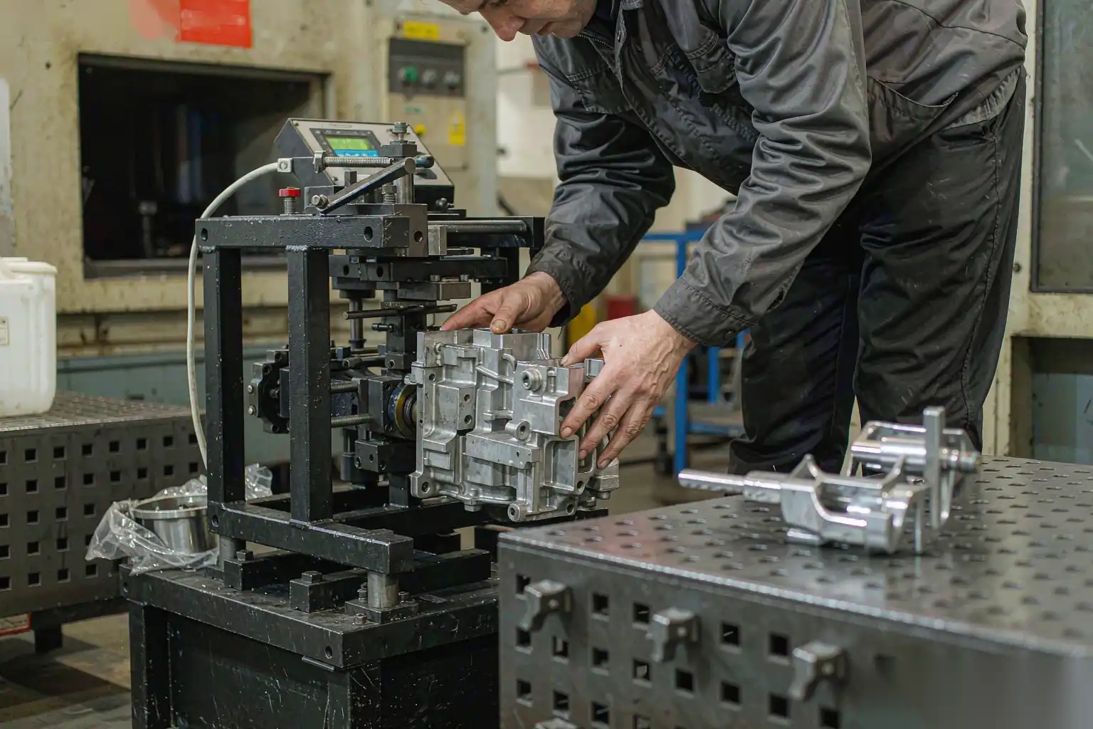
Pressure-decay testing. The part is pressurized with air to a set pressure, isolated, and the pressure drop over a fixed time is measured. A drop larger than the allowable loss fails the part. It is cheap, fast, and non-destructive, and it is the workhorse for most aluminum die cast housings and covers.
Helium mass-spectrometer testing. The part is exposed to helium at a tracer pressure and a mass spectrometer sniffs for helium escaping through the wall, or the part is placed in a helium atmosphere and the accumulated helium inside is measured. Helium’s small molecule and the spectrometer’s sensitivity push detection to leaks far below what air decay can see, down to the 1e-6 mbar per liter per second range and below.
Mass-flow testing. Instead of watching pressure fall, a flow meter directly measures the volume or mass of gas passing through the part at a fixed differential pressure. It is intuitive (the gauge reads a leak rate directly) and it is robust for parts with large internal volumes where pressure-decay sensitivity is poor.
Comparison:
| Method | Typical sensitivity (mbar l/s) | Speed | Cost | Best use |
|---|---|---|---|---|
| Pressure decay | 1e-2 to 1e-3 | Fast, 5 to 30 s | Low | General housings, covers |
| Mass flow | 1e-2 to 1e-4 | Fast, 5 to 30 s | Low to medium | Large volumes, direct rate |
| Helium spec | 1e-6 to 1e-8 | Slow, 30 to 120 s | High | Sealed units, fuel, brake, medical |
The choice is driven by the leak rate the application can tolerate, not by what equipment is on the shelf.
Specification levels by application
Leak spec is written in leak rate units such as mbar per liter per second (mbar l/s), or equivalently cubic centimeter per minute at a reference, or sccm. The number must come from the function, not from a default.
Rough guidance for die cast aluminum parts:
- Non-pressure decorative or structural covers with no fluid: a coarse seal, often 1e-2 to 1e-1 mbar l/s, just to exclude open porosity.
- Water-jacket or coolant passages: around 1e-3 to 1e-4 mbar l/s to avoid slow weep over service life.
- Pneumatic or low-pressure air chambers: 1e-4 to 1e-5 mbar l/s.
- Compressor or refrigerant-containing bodies: 1e-5 to 1e-6 mbar l/s, where helium is often justified.
- Fuel, brake, or medical sealed components: 1e-6 mbar l/s and tighter, essentially always helium-based.
Two traps in spec writing. First, do not specify a helium-grade leak rate and then test with air decay; you will either fail good parts or, worse, pass them. Second, define the test pressure. A leak rate scales with pressure, so “leak less than 1e-4 at 3 bar” is a different requirement from the same number at 0.5 bar. State both.
The defect interaction is the key point: the achievable leak floor is set by the casting, and the spec must be reachable by the process. The defect and solution guide at aluminum die casting defects and solutions explains the porosity and cold-shut mechanisms that create leak paths; if the process cannot make them absent, no test spec will save the part.
How porosity sets the leak floor
This is the part most spec writers miss. A leak test does not create a leak floor; the casting’s porosity does. Even a “sound” aluminum die casting contains a distribution of micro-pores from gas entrainment and shrinkage. Individually these pores may be below the detection limit of X-ray, but connected through the wall they form a tortuous path that lets gas or fluid creep through at a rate that depends on pore size, connectivity, and wall thickness.
Implications:
- There is a physical minimum leak rate for a given alloy, wall thickness, and porosity level. You cannot test a heavily porous part to a helium-grade spec; it will always leak.
- Reducing the measured leak rate means reducing porosity at the source: better gating, venting, vacuum assist, and thermal balance, not tightening the test threshold.
- A part that passes air decay at 1e-3 may still weep over years because the connected micro-porosity passes a slow, time-dependent leak the short test does not capture. Long-duration soak tests catch this but cost cycle time.
- Wall thickness matters. A 3 mm wall leaks less than a 1.5 mm wall at the same porosity, so the leak floor is a function of section as well as alloy.
The practical conclusion: set the leak spec after measuring the as-cast porosity floor, not before. If the floor is 1e-3 mbar l/s and the function needs 1e-5, the answer is a process change (vacuum, gating, possibly a densifying secondary operation), not a more sensitive tester. Yield and scrap reduction strategy at die casting yield scrap reduction covers how to attack porosity at the source so the leak floor drops.
Test fixture design and cycle time
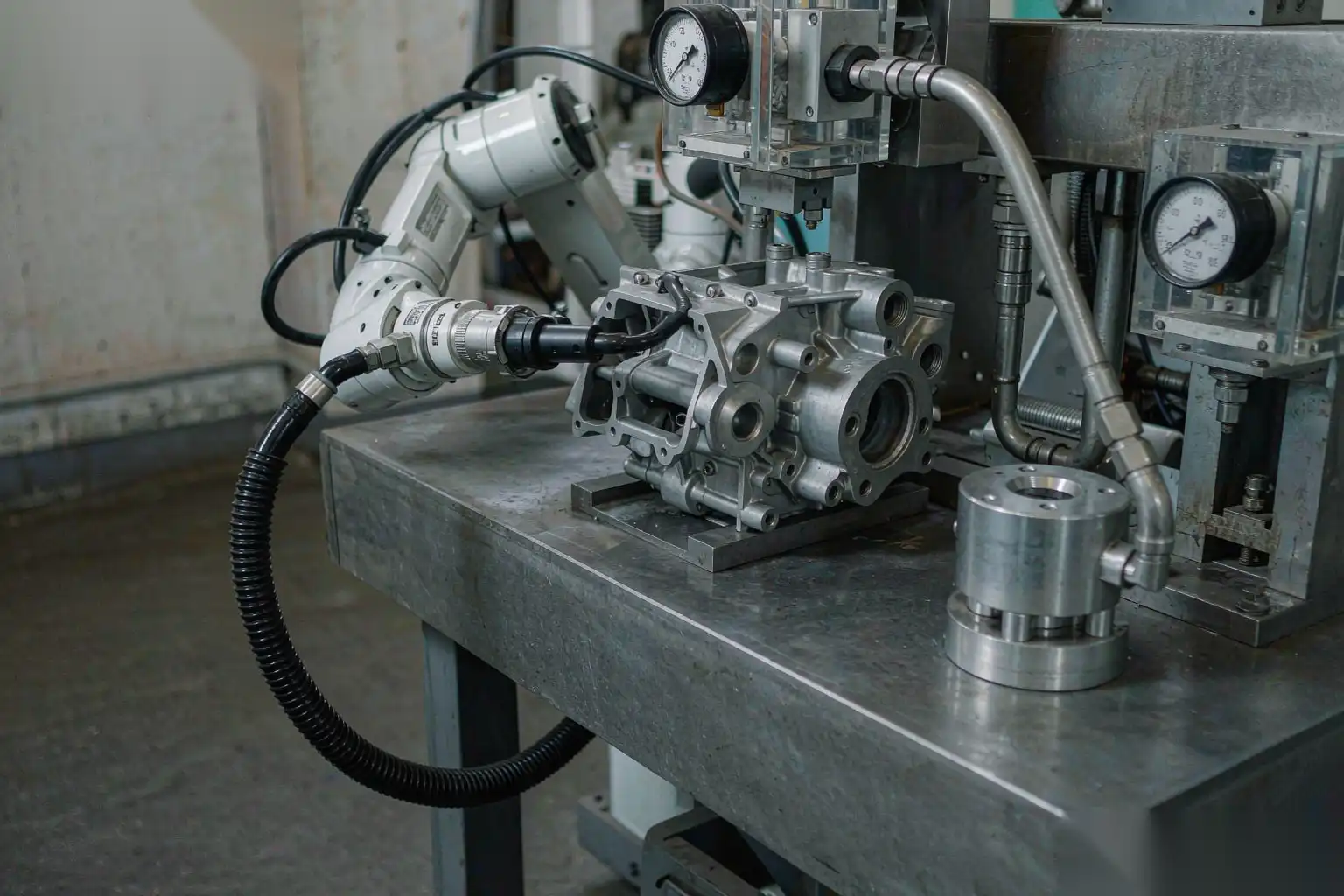
The fixture, not the tester, usually decides whether leak testing fits the line rate. A poor seal between the part and the test nest wastes most of the cycle in clamp, stabilize, and vent.
Design rules we apply:
- Seal on machined or trimmed faces, never on a draft-bearing as-cast surface, because draft makes a reliable seal impossible. If the only available seal face is as-cast, machine a seal lands there.
- Minimize the test volume. The larger the internal volume, the longer pressure stabilization takes before a decay reading is valid. Use fillers or plugs to block unused cavities and shrink the volume under test.
- Size the clamp force to the test pressure times the seal area, with margin, but avoid distorting a thin wall, which would open a false leak path during the test and close it after release.
- Provide a fast-fill path and a separate slow-test path so the part pressurizes quickly but stabilizes cleanly.
- Include a reference leak (a calibrated orifice) in the loop so the tester self-checks; a dead tester that reads zero is worse than no test.
- Account for part temperature. A warm part from trimming or just out of a wash expands the gas and biases decay; let parts reach test temperature or temperature-compensate the algorithm.
Cycle time budget for an in-line cell:
| Step | Typical time |
|---|---|
| Load and clamp | 3 to 8 s |
| Fill and stabilize | 5 to 15 s |
| Test (decay or flow) | 5 to 30 s |
| Vent and unclamp | 2 to 5 s |
| Total | 15 to 60 s |
Helium cycles run longer because of evacuation and sniff time. The cell must therefore be balanced so leak test does not become the bottleneck; parallel stations or a rotary indexer often pay for themselves.
False rejects from surface films and moisture
A frustrating leak-test failure mode is the false reject: the part is sound, but the test says leak. The usual cause is not the metal but a film on it.
- Cutting fluid, polish compound, or wash residue left in a passage can temporarily block a pore during the test and then later dissolve or dislodge, or conversely trap gas and mimic a leak. Clean parts to a defined standard before test.
- Moisture in a blind hole flashes to vapor under test pressure and reads as a decay, a classic warm-and-wet false fail. Dry parts, especially after washing, before they reach the tester.
- Lint or die lube skin across a seal land prevents the fixture from sealing, so the tester sees a gross leak that is really a dirty seat. Inspect and wipe seal lands.
- A part still warm from a previous operation holds expanded gas; the decay reflects temperature, not leakage. Temperature-match or compensate.
- Debris in the fixture’s seal groove from the previous part causes intermittent gross leaks. Build in seat cleaning or use disposable seals.
These are process-discipline problems, not instrument problems. The secondary operations guide at die casting secondary operations guide covers the cleaning, trimming, and machining steps that must be controlled so the part arrives at the leak tester in a testable state.
Automating leak test in a finishing line
Leak testing earns its place when it sits inside the automated line rather than at a separate bench, because only then does its data close the loop with grinding, washing, and inspection.
An automated leak station in a DZ finishing line typically:
- Receives the part from the robotic grinding or washing cell on a conveyor or rotary table, with no manual handling that could introduce contamination.
- Clamps in a sealed nest, runs the chosen method (decay or mass flow for volume parts, helium for sealed units), and sorts pass, fail, and ambiguous into separate lanes.
- Logs the leak rate per part against the part serial or cavity, feeding an SPC chart so a drift in porosity shows up as a creeping leak-rate trend before parts fail.
- Triggers a process response. A rising mean leak rate points upstream to porosity, gating, or venting, and the line can flag the affected cavity for maintenance.
- Hands accepted parts forward to final inspection or packing without a touch.
The integration matters because leak rate is the most direct functional proxy for internal soundness. A CMM tells you about geometry; a leak test tells you the part will not weep. In a pressure-bearing die cast component the leak result is the one number the customer actually cares about, so it deserves to be automatic, logged, and tied to the casting process that controls it.
Building a leak-test plan that holds
A workable plan:
- Set the leak spec from function and test pressure together, in mbar l/s, with the method stated.
- Measure the as-cast porosity floor first; if the spec is below the floor, fix the casting process before buying a finer tester.
- Seal on machined lands, minimize test volume, and self-check the tester with a reference leak.
- Control cleaning and drying so films and moisture do not cause false rejects.
- Automate the station in-line and log leak rate by cavity to drive upstream maintenance.
DZ Machinery builds die casting and robotic finishing lines with integrated leak-test stations that sort, log, and feed leak-rate trends back to the casting process, so pressure-bearing components leave the cell verified rather than hoped. Talk to our engineering team about your part’s pressure class and drawing, and we will size the test method, fixture, and line integration for your rate.