Measuring Surface Roughness on Castings: Ra, Rz and Operator Error
Why roughness numbers on castings lie
Surface roughness looks like a simple number. You touch a stylus to a part, the machine prints Ra = 1.6, and everyone is happy. On a die casting, that number is often wrong by a factor that matters, and nobody knows because the error is buried in the measurement method rather than the part. Cast surfaces are rough, non-uniform, and sometimes soft enough that the instrument itself changes them during the test. A value that swings from 1.2 to 3.4 micrometer Ra depending on where you put the stylus, which cutoff you chose, and how hard you pressed is not a measurement. It is a coin flip wearing a lab coat.
This article sets out what Ra, Rz, and Rt actually describe, why the cutoff wavelength decides whether your number is real, how the stylus tip smears soft aluminum, how as-cast compares to polished, and how to write a roughness specification that a robotic finishing cell can actually hold. The goal is a measurement you can defend when a customer disputes a shipment.
Ra, Rz and Rt: what each parameter tells a finisher

These three parameters answer different questions, and a finisher who only watches Ra misses most of them.
- Ra, arithmetic average roughness. It is the average absolute deviation of the profile from the mean line over the evaluation length. Ra is forgiving. It averages out the deep scratches and the tall peaks, so two surfaces with very different spike structures can share the same Ra. For a finisher, Ra tells you about the general texture but hides the worst defect.
- Rz, average maximum height of the profile. Defined in the common ISO 4287 sense as the average of the five largest peak-to-valley heights within the evaluation length (some standards use the ten-point height Rz; confirm which your gauge reports). Rz is sensitive to the occasional deep groove. If your customer seals against a face and one deep scratch breaches the gasket line, Rz catches it while Ra stays calm.
- Rt, total height of the profile. The single largest peak-to-valley distance in the traced length. Rt is the worst-case number and the one that predicts leakage paths and coating thin spots.
The practical ordering for a casting finisher is: Ra for incoming cosmetic texture, Rz for seal and bond surfaces, Rt for the hard failure limit. A surface can read Ra 0.8 after polishing yet still carry an Rt of 12 micrometer from a single buried inclusion scratch. If you specified only Ra, that part passes your gauge and fails in the field.
A compact comparison:
| Parameter | What it weights | Failure it predicts | Typical as-cast Al | Typical polished Al |
|---|---|---|---|---|
| Ra | Average texture | General cosmetic | 3.2 to 6.3 micrometer | 0.2 to 0.8 micrometer |
| Rz | Deep peaks and valleys | Seal breach, bond loss | 15 to 30 micrometer | 1.5 to 4 micrometer |
| Rt | Worst single event | Leak path, coat thin spot | 25 to 60 micrometer | 3 to 10 micrometer |
Cutoff wavelength: the setting that makes or breaks the number
The cutoff (sampling) wavelength lambda c filters the profile into roughness and waviness. Choose it wrong and you either count the warpage as roughness or you average the real texture into nothing.
The standard default for most metals is 0.8 mm, but that default is a habit, not a rule. The cutoff must be matched to the dominant spacing of the surface features:
- Too short a cutoff, for example 0.25 mm on a coarse as-cast face, chops the profile into fragments and under-reports Ra because the filter never captures a full asperity cycle.
- Too long a cutoff, for example 2.5 mm on a finely polished face, lets waviness and form enter the roughness band, inflating Ra with low-frequency error that is not texture at all.
- ISO 4288 gives a rule: the cutoff should be at least five times, preferably more, the mean asperity spacing Sm of the surface. Measure Sm first, then set lambda c.
On an as-cast aluminum die surface the asperity spacing is often 0.2 to 0.5 mm, so a 0.8 mm or even 2.5 mm cutoff is appropriate. On a robot-polished face with Sm around 0.05 mm, 0.25 mm is correct. We document the cutoff on the inspection plan next to the Ra target, because two labs reporting “Ra 1.6” at different cutoffs are not measuring the same thing.
The evaluation length is normally five times the cutoff (so five 0.8 mm traces for a 4 mm evaluation at 0.8 cutoff). Shortening the evaluation to save time on a non-uniform casting increases scatter dramatically, because cast texture varies point to point.
Stylus tip radius and the soft-aluminum smearing problem
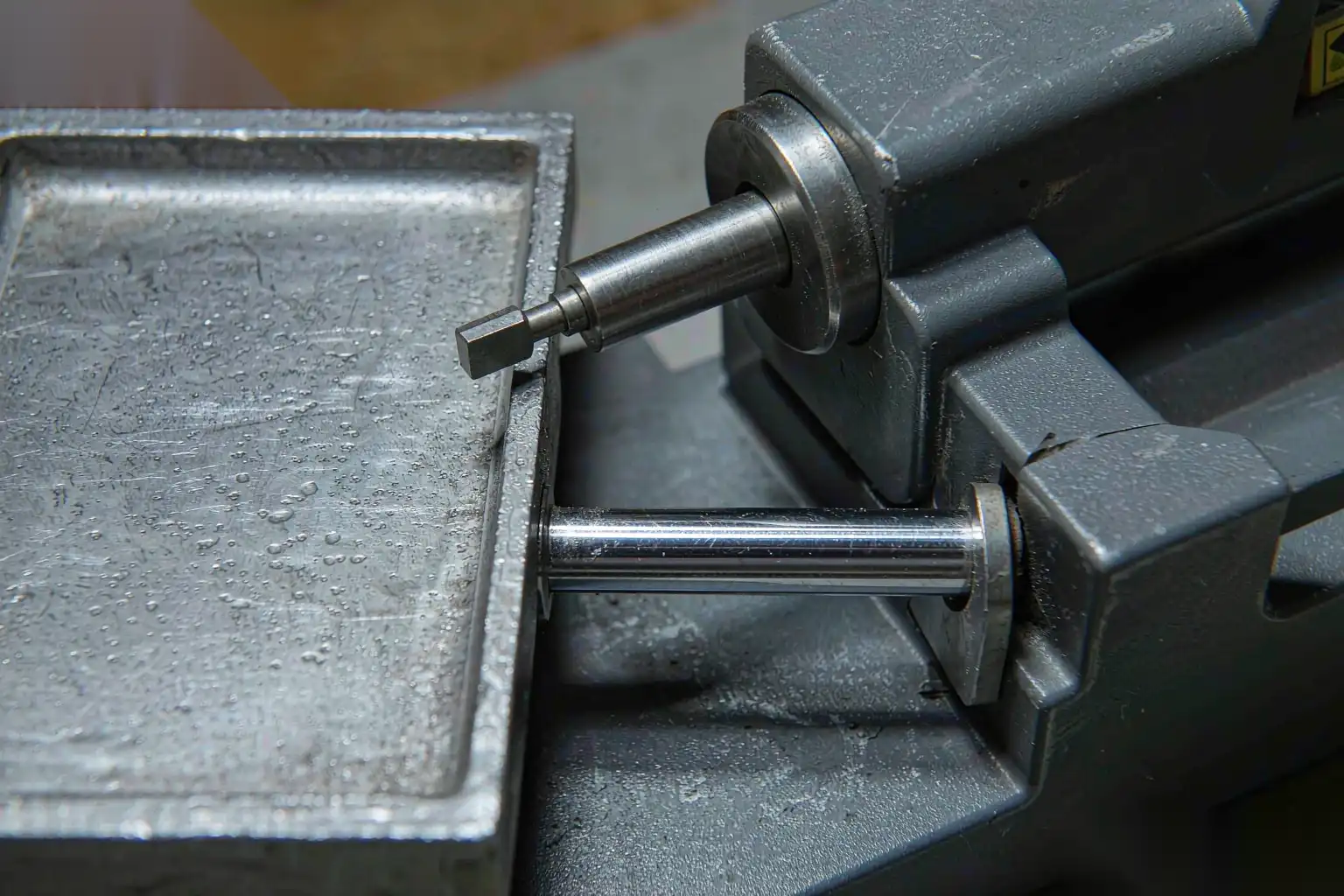
Aluminum is soft and the as-cast skin is a different microstructure from the bulk. A stylus that would be ideal on hardened steel can plow a groove through as-cast aluminum, dragging material aside and leaving a smeared channel that is smoother than the true surface. The result is an Ra that is too low and a profile that has been physically altered by the test.
Controls that keep the stylus honest:
- Tip radius. A 2 micrometer radius diamond tip is common for fine work; 5 to 10 micrometer ruby or diamond tips are used for coarse cast surfaces. A sharp tip on a coarse surface bottoms out in the valleys and over-states peaks; a blunt tip bridges fine texture and under-reports it. Match the tip to the expected Ra band, not to the gauge’s sharpest option.
- Measuring force. Keep the stylus force low, typically a few millinewtons, and verify the trace is repeatable on a second pass at the same spot. If the second pass differs by more than 10 percent, the tip is deforming the surface.
- Direction of trace. Roughness on a cast face is anisotropic because of flow and ejection marks. Always trace perpendicular to the dominant lay, or specify the lay direction in the plan. Tracing with the lay can halve the apparent Ra.
- Avoid measuring directly over inclusions or porosity. A probe dropping into a pore reads a false valley; screen the spot visually first.
- For very soft or delicate as-cast skins, consider a non-contact optical profiler. It avoids smearing but requires managing reflectivity, and it cannot reach into shadowed grooves the way a stylus can.
The surface finish standards reference at die casting surface finish standards lists the Ra bands we treat as achievable per casting class and how they map to finishing method.
Measuring as-cast versus polished surfaces
The as-cast face and the polished face are two different measurement problems, and the plan must treat them separately.
As-cast measurement:
- Expect high scatter. Take five to ten traces across the face and report the mean and range, not a single touch.
- Watch for the die skin. The chilled surface layer is finer than the subsurface; if grinding has just nicked through it, the local Ra jumps.
- Draft and curvature mean the stylus meets the surface at a varying angle; keep the part fixtured so the measured region is roughly normal to the stylus axis.
- Porosity near the surface reads as spiky Rt. Separate “roughness” from “defect” in the report.
Polished measurement:
- After robotic polishing the surface is anisotropic and fine; use a short cutoff and a sharp tip, and trace across the polish lay.
- A buffed face can read misleadingly good on Ra while hiding sub-surface micro-cracks from over-aggressive force. Pair Ra with an Rt limit.
- Verify the polish did not thin a wall or open a pore; roughness alone will not catch that.
The finishing options overview at aluminum die casting finishing options describes which processes move a surface from as-cast texture into a polished band and what Ra each typically delivers on a DZ cell.
Operator error: the dominant source of bad roughness data
In our audits of casting lines, instrument error is rarely the problem. Operator error is. The same part measured by two technicians on the same gauge returns numbers that differ more than the process variation does. The usual causes:
- No fixed measurement location. The operator touches wherever the part is handy, so they average different texture regions. Fix the spot with a fixture or a marked grid.
- Wrong or unset cutoff. The gauge remembers the last job’s cutoff; nobody changed it.
- Dirty surface. Cutting fluid, polish compound, or oxide left on the part adds or hides texture. Clean with the same solvent every time.
- Uncalibrated gauge. Roughness standards drift; the reference block should be checked against a calibrated specimen on a schedule.
- Ignoring the skid. Skidless (probe arm) versus skid-type gauges measure relative to different references; mixing them across a supply chain produces disputes.
- Single trace instead of a mean of several. Cast texture variation demands multiple traces.
The cure is a written standard operating procedure with a photo of the measurement location, the cutoff, the tip, the force, the number of traces, and the solvents. We hand that procedure to both the casting line and the customer’s incoming inspection so both sides generate comparable numbers. When a claim arrives that a shipment is “too rough,” the first question is whether both parties used the same cutoff and location, not whether the parts changed.
Setting a roughness spec a robotic cell can hold
A specification is only useful if the process can hold it and the gauge can verify it. For a robotic grinding and polishing cell, the achievable band depends on the abrasive sequence, the force control, and the part geometry.
Guidance for writing the callout:
- Specify Ra and Rz together, never Ra alone for a seal or bond face. Add an Rt limit for critical leak paths.
- State the cutoff, the trace direction relative to lay, the number of traces, and the location. A bare “Ra 1.6” on a drawing is incomplete.
- Tier the spec by function: cosmetic non-contact faces can be loose (Ra 3.2), handled or sliding faces medium (Ra 1.6), seal faces tight (Ra 0.8 with Rz limit), and polished decorative faces per the customer’s sample (Ra 0.2 to 0.4).
- Confirm the starting as-cast band so the cell knows how much stock to remove. If the incoming Ra scatters from 3.2 to 8.0, the cell must be tuned for the worst case, which costs cycle time. Tightening the as-cast process upstream is cheaper than over-polishing downstream.
- Set the cell’s force and feed so the achieved Ra sits in the middle of the band, not at the edge, leaving room for gauge uncertainty.
How achievable bands map to process:
| Target Ra (micrometer) | Process path on DZ cell | Typical use |
|---|---|---|
| 3.2 to 6.3 | As-cast, trim only | Hidden structural faces |
| 1.6 | Coarse belt grind | Bearing-adjacent, handled |
| 0.8 | Fine belt plus buff | Seal and gasket faces |
| 0.2 to 0.4 | Multi-stage polish, wax feed | Decorative faucet bodies |
The throughput and uptime factors that decide whether a cell can hold that spec shift after shift are covered in robotic cell OEE uptime improvement, because a cell that loses its abrasive consistency or its force calibration mid-shift will drift out of the Ra band before anyone notices.
Closing the loop from roughness to process control
Roughness data should drive the finishing cell, not just fill a report. When Rz on seal faces trends upward, the abrasive belt is loading or glazing and needs dressing or replacement. When Ra scatter widens, the force-control compliance or the fixture locating is drifting. When Rt spikes on individual parts, suspect a subsurface inclusion or a local porosity breakthrough that the grinding exposed. Each of these is a process signal, not a measurement curiosity.
DZ Machinery builds robotic grinding and polishing cells with automatic abrasive change, wax feed, and per-feature force control that hold the Ra and Rz bands your assemblies require, and we document the cutoff, tip, and trace procedure so your incoming inspection and ours speak the same language. Talk to our engineering team about your surface specification and part drawings, and we will set up the measurement plan and the cell together.