What Is Robotic Deburring Programming?
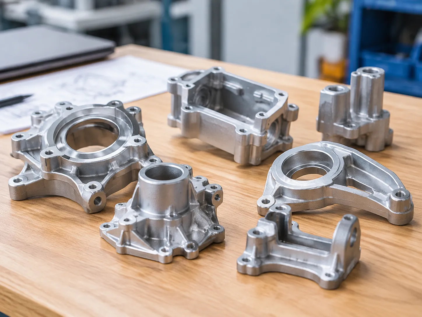
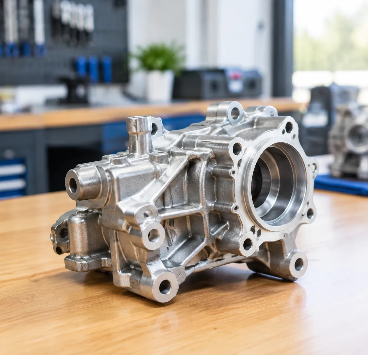
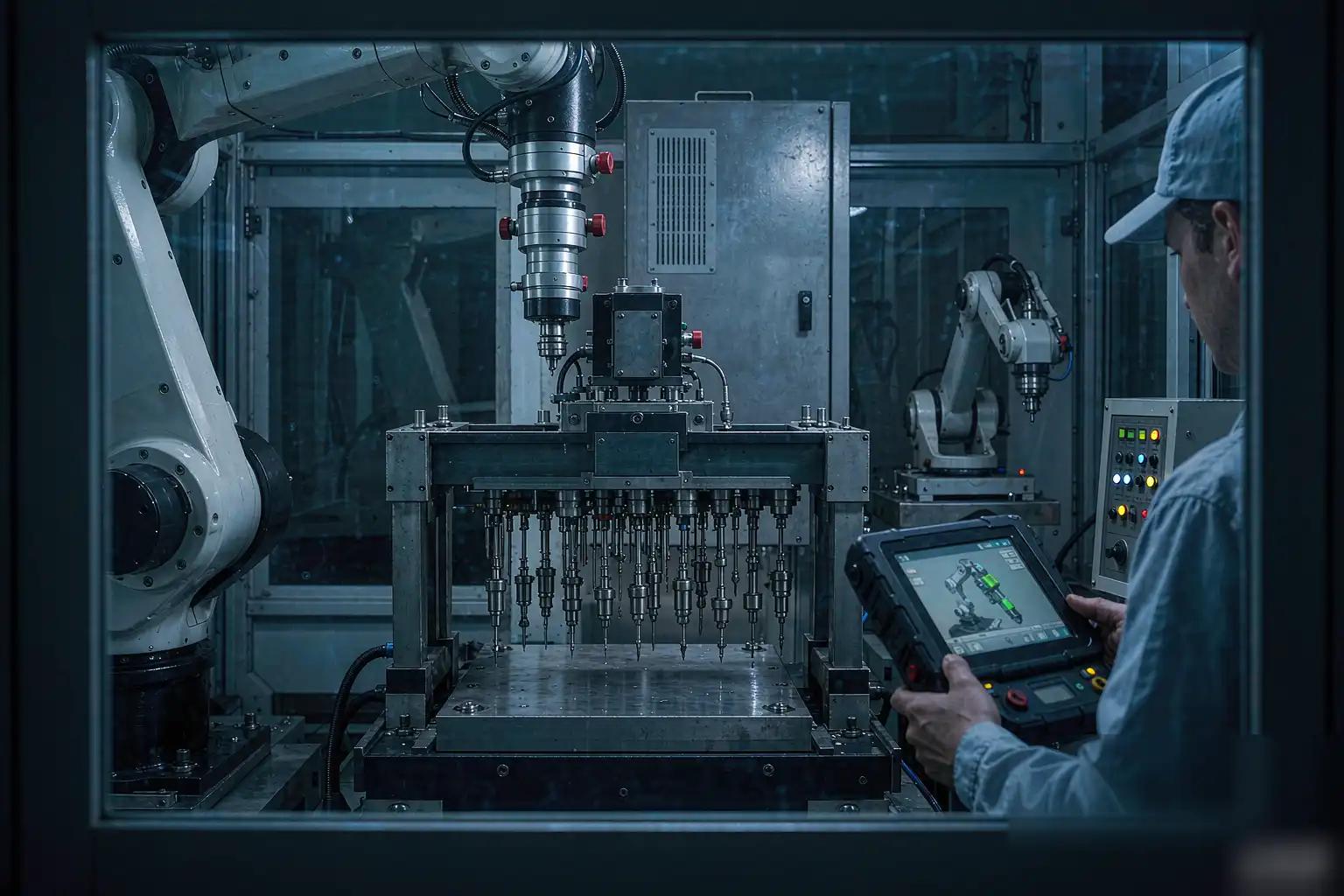
Robotic deburring programming is the process of configuring an industrial robot to remove burrs, flash, and sharp edges from machined parts. It combines robot motion paths, spindle or brush tool control, and force feedback into a single repeatable routine. A well-structured program reduces scrap and frees operators from tedious hand finishing work. Beginners should treat it as a workflow, not one command.
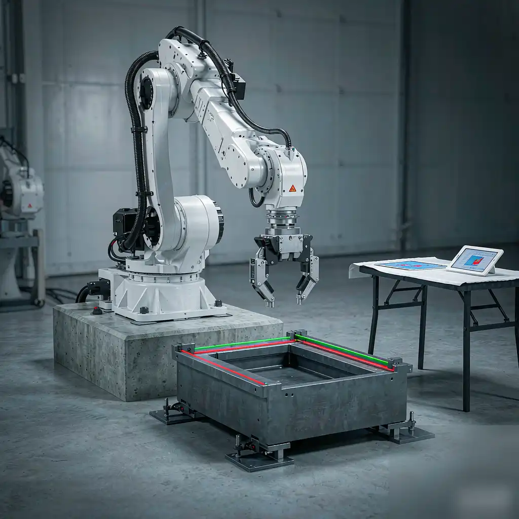
This discipline sits at the intersection of mechanical setup and software logic. The program decides where, how hard, and how long contact happens. Learning the programming side early pays off after the cell is built. The sections below break the task into clear steps.
Why Your Cell Needs a Programming Plan First
Starting without a plan leads to inconsistent edges and damaged fixtures. A clear programming plan defines the part geometry, the access angles, and the contact force you need before coding. Therefore, you save hours of rework by mapping the process before you touch the teach pendant. Moreover, a documented plan helps the next operator understand your logic.
Before writing code, capture these basics in a one-page sheet kept near the cell. The list below is a practical starting checklist for most deburring jobs.
- Part material, hardness, and surface condition
- Burr size, location, and how consistent it stays
- Required cycle time and daily production volume
- Available robot reach, payload, and controller brand
- Existing fixtures, clamps, and locating references
Step 1: Choose the Right Robot and Mounting
Select a six-axis articulated robot with enough reach to cover the part without extreme joint angles. Floor, wall, or inverted mounting changes your approach vectors, so decide early in the layout. A payload margin of at least 30 percent protects you when you add a heavy deburring spindle later. Finally, verify the controller supports external force-torque inputs.
Reach matters more than raw speed for deburring work. If the robot stretches to its limit, path accuracy drops and wear rises. Pick a model where the part sits comfortably inside the working envelope.
Step 2: Select the Deburring Tool and Media
The tool defines your finish quality more than the robot does in most cases. Rotary burrs suit hard alloys, while compliant brushes work better on fragile edges and thin walls. Match the spindle speed to the media you chose, then document the combination clearly. In addition, keep spare media on hand because wear changes your contact force over time.
Choose between a compliant head and a rigid one. Compliant tools absorb small variations and protect delicate parts. Rigid tools cut aggressively but demand tighter fixturing. Match the tool to your part’s weakest feature.
Step 3: Mount and Align the Workpiece Fixture
A stable fixture is the foundation of accurate robotic deburring programming. Clamp the part so vibration cannot shift it during contact with the tool. Use locating pins to guarantee repeatable positioning within 0.1 mm on every load. As a result, your taught points stay valid across hundreds of parts without reteaching.
Check the fixture for wear before blaming the program. Loose clamps and worn locators cause the same symptoms as bad paths. Inspect and tighten it during daily startup checks.
Step 4: Establish Your Coordinate Frames
Define the user frame on the fixture and the tool frame on the spindle nose. These frames let the robot interpret paths relative to the part, not the floor or the robot base. When the fixture moves, you only update one frame instead of editing every point. Consequently, changeovers become far faster and far less error prone.
Calibrate the tool frame carefully, because a fraction of a millimeter error propagates into every path you teach. Repeat calibration after any tool change. Accurate frames are the quiet hero of consistent deburring.
Step 5: Teach the Approach and Retract Points
Always teach safe approach points above the part before moving into contact. A linear move from clear air prevents crashes into clamps, neighbors, or the part itself. Then define the retract path so the tool lifts before traveling sideways to the next feature. This discipline protects both tooling and operators during every cycle.
Plan approaches from the direction with the best visibility and clearance. Avoid paths that force the wrist into a singularity near contact. Smooth, separated moves make later troubleshooting simpler.
Step 6: Program the Deburring Path
Now build the actual contact path along the burr edge with steady motion. Use a consistent feed rate and keep the tool normal to the surface for even material removal. Most beginners start with a simple linear or circular pass, then refine it after the first part. However, complex contours need spline or process commands from your controller.
Break long edges into smaller segments you can tune individually. This helps you find where finish quality drops. Small, organized paths beat one giant confusing routine.
Step 7: Apply Force Control for Consistent Contact
Passive or active force control keeps pressure constant as the media wears down. Set a target contact force and let the robot comply with surface variation automatically. The table below shows typical starting values for common materials. Adjust gradually and record what works for your specific part.
Without force control, the first part and the hundredth part look different. Media wears, fixtures settle, and tolerances drift across a batch. Force feedback closes that gap and keeps edge quality steady.
| Material | Typical Start Force | Why |
|---|---|---|
| Aluminum | 15 N | Soft metal needs low force to avoid gouging the edge |
| Steel | 30 N | Higher force cuts harder burrs reliably and quickly |
| Die cast zinc | 20 N | Brittle flash breaks cleanly with moderate pressure |
| ABS plastic | 10 N | Low force prevents melting and edge cracking |
FIRST STEP — begin each new material at the lowest table force, then raise it slowly until the burr clears.
Step 8: Tune Spindle Speed and Feed Rate
Spindle speed and feed rate together control surface finish and the heat you generate. Too fast a feed leaves streaks, while too slow simply wastes cycle time and money. Test a corner first, then apply the setting to the full path once it looks right. Furthermore, log the values so future parts benefit from your tuning effort.
Different media have different happy speeds, so do not copy settings blindly. A brush may prefer lower rpm than a carbide burr on the same alloy. Build a reference table of proven combinations over time.
Step 9: Add Safety Zones and Interlocks
Program protective stops and require a guard interlock before motion starts. Light curtains and door switches must halt the robot if someone breaches the boundary. Because deburring throws debris, enclose the area and use extraction. Safety is never optional.
Define reduced-speed zones near load doors and manual stations. These let operators work close without disabling the whole cell. Review the safety logic with your plant supervisor before commissioning. A safe cell is a cell that stays running.
Step 10: Run a Dry Cycle, Then Measure and Validate
Run the program with the tool disabled to confirm motion and clearance first. Watch for tight joint angles or positions near the robot’s limits. Then run one real part at reduced speed and inspect the edge under good light. If the burr remains, increase force slightly or add a second pass.
Use a profilometer or simple edge gauge to confirm the edge meets specification. Photograph the first article for your quality record. When results vary part to part, check fixture wear before changing the program. Consistent measurement closes the loop on robotic deburring programming.
Common Mistakes Beginners Should Avoid
New programmers often over-force the tool, hoping to cut faster, which destroys edges instead. Another error is skipping the user frame, making every later edit painful and confusing. Also, neglecting debris extraction shortens both tool life and robot life noticeably. Learn these lessons on scrap parts, never on live production runs.
A fourth mistake is tuning one perfect part and assuming the batch will match. Real batches have variation that your program must absorb through force control. Test at least five parts before declaring the process ready. Patience here prevents expensive surprises on the floor.
When to Upgrade Toward Integrated Solutions
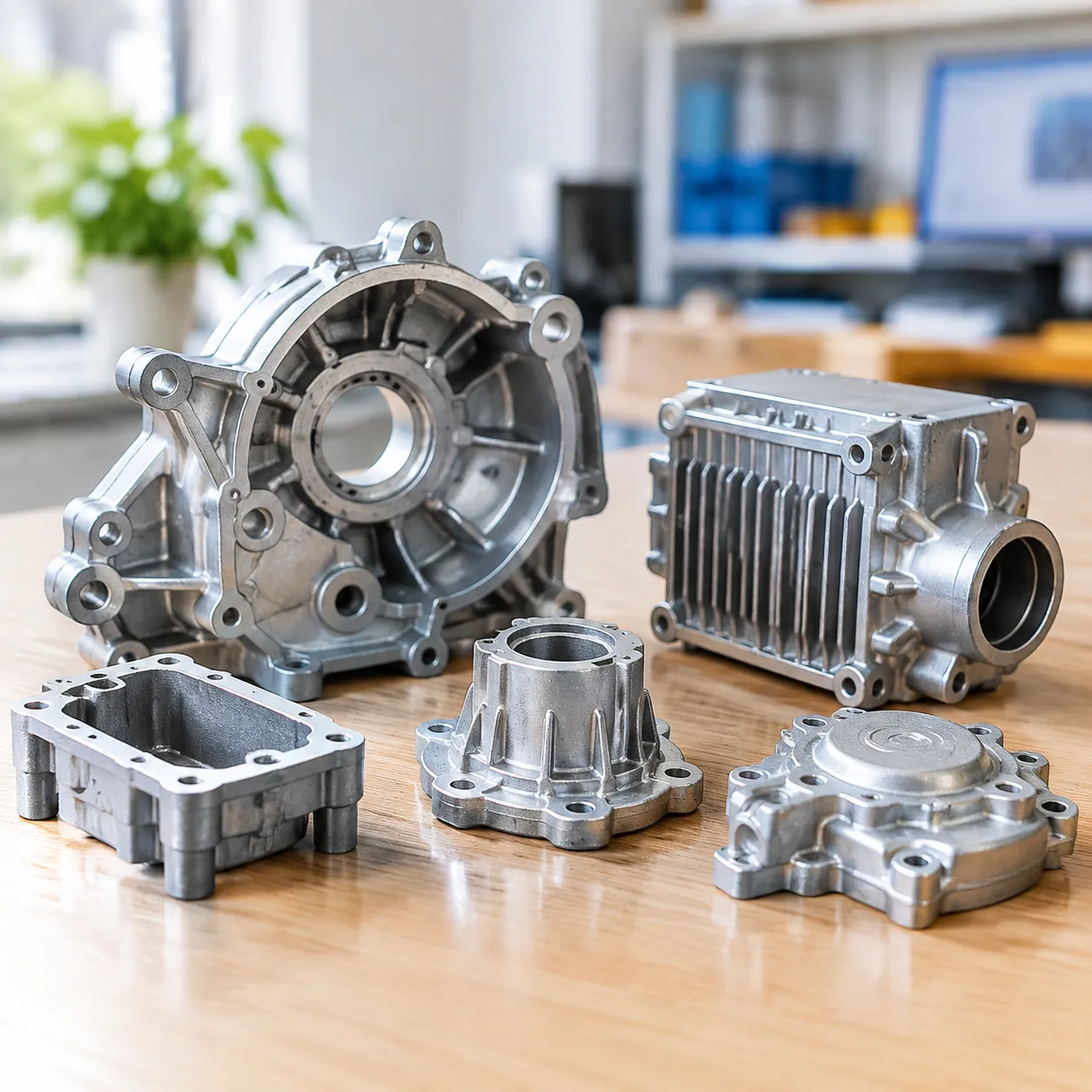
As volumes grow, manual teaching becomes the bottleneck for your otherwise capable cell. Integrated systems add auto tool changing, vision locating, and centralized recipe management. For high-volume castings, review robotic surface finishing solutions for the die casting industry to see a production-ready approach. Such upgrades pay back through uptime and consistency rather than speed alone.
Integration also reduces the skill needed to run the cell day to day. Recipes can be selected from a menu instead of reprogrammed by an expert. This protects your operation when key staff are unavailable. Plan the upgrade path while the cell is still small and simple.
WHY IT PAYS — a programmed cell holds the same edge quality on part one and part ten thousand, cutting scrap and freeing operators.
Connecting Deburring to Full Cell Integration
Deburring rarely sits alone on a modern factory floor for long. Loading, washing, inspection, and marking usually share the same robot and controller. Understanding surface finishing robot integration essentials helps you design one coherent system for the whole line. A unified program is easier to maintain and train than scattered scripts.
Think about data flow, not just motion, when you integrate. The deburring result should inform the inspector downstream automatically. Shared frames and naming make that communication possible. Strong integration turns machines into one smart process.
Automotive Parts Bring Tighter Requirements
Automotive suppliers demand traceable, repeatable edge quality on every single shipment. robotic deburring solutions for automotive parts typically add in-process gauging and automatic compensation. If your parts feed that supply chain, build the measurement step into the program from day one. This prepares you for audits without retrofitting later.
Documentation matters as much as the edge itself in this sector. Keep force, speed, and result logs tied to part serial numbers where possible. Customers will ask for that evidence during qualification. A program built with traceability in mind wins those contracts.
This article is for general guidance only; confirm process parameters with the equipment supplier for your specific parts.