Trimming Die Design and Gate/Runner Cutting for Die Castings
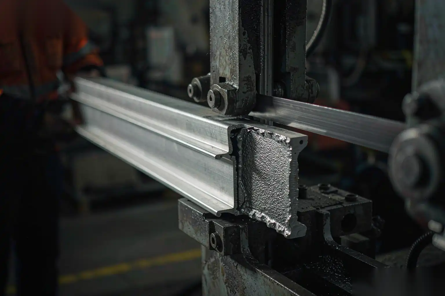
The trim die is the unsung workhorse of a die casting line. It sits between the casting machine and every downstream operation, and it does the dirty job of separating the part from the gate, runner, and overflows while trimming the parting-line flash. Done well, it turns a shot into a clean, located part ready for CNC and robotic finishing. Done poorly, it leaves torn edges, distorted faces, and flash stubs that a robot cannot reliably follow, pushing labor back to a person with a file.
This article is a design reference for trimming dies and gate cutting, written for the tooling engineer laying out the trim station. We cover why trim dies matter beyond cost, how to align the trim to the parting line, punch and clearance design for thin flash, single-hit versus progressive tooling, handling gates and overflows, how trim quality sets up robotic deburring and polishing, tool steel and wear, and the cycle-time impact on the cell.
Why trim dies matter more than they look
It is tempting to treat trimming as a commodity step: a press, a punch, a done part. In practice the trim die sets the quality floor for everything after it.
What a good trim die delivers:
- A clean separation of part from gating, with no residual gate stub that later breaks off inside a finished assembly.
- A consistent parting-line flash edge, uniform in thickness and location, so the deburr cell meets the same edge every cycle.
- A located, supported part that does not distort under trim force, preserving the datums CNC and robotics rely on.
- A fast, repeatable hit that keeps pace with the casting machine rather than bottlenecking it.
What a poor trim die costs:
- Torn or ragged parting lines that require manual touch-up, the single biggest source of labor on a line.
- Distorted thin walls from uneven cutting force or poor support, which then fail flatness at machining.
- Inconsistent flash that defeats automated edge-following, because the robot cannot find a stable path.
- Gate stubs left proud of the surface that become stress risers or cosmetic defects after plating.
For the parting-line and gate-removal fundamentals this builds on, see our aluminum die casting gate removal and parting line reference, which covers where flash originates and how the trim die should meet it.
Aligning the trim cut to the parting line
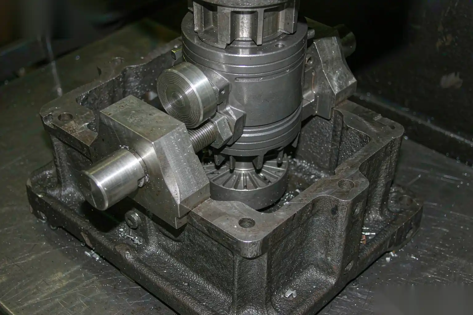
The trim die cuts along the parting line, so its cutting profile must be a faithful copy of that line projected onto the trim plane. The first design rule is to design the trim die from the same CAD the casting die used, not from a redrawn approximation.
Principles:
- The trim punch profile should match the casting parting line exactly, including every radius and step, so the cut lands on the intended plane.
- Where the parting line runs across a flat face, the trim should cut cleanly on that plane and leave a minimal, uniform flash land for the robot to break.
- Avoid designing a parting line that curves in three dimensions if a planar or simple stepped line will do; complex trim profiles are harder to grind and maintain.
- Keep the trim line away from cosmetic surfaces. If the parting line crosses a visible face, the trim seam will be visible regardless of how good the die is, so the casting design should move it to a hidden edge.
A trim die that is misaligned with the parting line by even half a millimeter will either leave a thick flash lip or cut into the part. Both are defects the downstream cell cannot fix cheaply.
Punch and clearance design for thin flash
The cutting action in a trim die is a shear, and like any shear it needs the right clearance between punch and die to produce a clean break rather than a tear.
Design rules that hold in production:
- Side clearance between punch and die: typically 3 to 8 percent of the material thickness being cut (the flash plus any thin gate web), adjusted for alloy. Aluminum and zinc flash cut cleanly at the low end; thicker gates need more.
- Too little clearance: the punch rubs instead of shears, accelerates wear, and leaves a burnished but torn edge.
- Too much clearance: the material draws and stretches before breaking, producing a ragged, burred edge and a larger deformation zone.
- Punch edge: keep a sharp, consistent land (0.1 to 0.3 mm) followed by relief; a rounded or chipped edge drags the flash instead of cutting it.
- For very thin flash (0.05 to 0.15 mm), the trim die acts almost like a planing operation; the support beneath the part must be rigid so the flash does not simply bend over rather than shear.
The goal is a cut, not a bend. If the flash is bending rather than shearing, the part leaves the trim die with a folded lip that no deburring brush will remove consistently.
Single-hit versus progressive trimming
Most die casting trim dies are single-hit: one stroke of the press cuts the part free from the gating and trims the perimeter in one action. That is correct for the vast majority of parts because it matches the casting cycle and keeps the cell simple.
When a progressive or multi-stage trim is justified:
- Very large or thin parts where a single hit would distort the casting under uneven load; a staged cut balances the force.
- Parts with internal gates or complex gating that must be removed in a sequence to avoid tearing a section.
- High-value parts where a controlled, low-distortion trim reduces downstream scrap more than the extra cycle costs.
Tradeoffs:
- Single-hit: lowest cycle, simplest tool, but demands a well-supported part and a clean gating layout.
- Multi-stage: more control, less distortion, but more press time and a more complex die with more maintenance points.
For high-volume consumer and automotive parts, single-hit trim at the casting cycle rate is the target; design the gating and the part support so a single hit is enough.
Handling gates, runners, and overflows
The trim die does not only cut the part perimeter; it also separates the gates, shears the runner where needed, and crops overflows. How these are handled determines whether the gating falls away cleanly or jams the die.
Design guidance:
- Place gates so the trim punch shears them in the same hit as the part, with a clearance zone that lets the gating drop free into a separate chute.
- Design runner and overflow remnants to fall away from the part, not to cling to it; a remnant caught on the part becomes a manual removal step.
- Use parting-line gates where possible, because they trim on the same plane as the flash; sub-gates or vestigial gates on a face require a separate cut or a milling op.
- Size overflows so their trim is a clean shear; oversized overflows add metal cost and trimming load for no benefit.
- Consider a knockout or air blast in the trim die to eject gating, keeping the nest clear for the next part and protecting the robotic pickup.
The trim die that drops a clean part and a separate pile of gating, with no mixed scraps, is the one that runs unattended. Mixed scrap forces an operator to sort, which is exactly the labor the cell is meant to remove.
How trim quality sets up robotic deburring and polishing
This is the connection that decides whether your finishing cell runs lights-out or not. A robot deburring cell follows an edge. If the edge it follows is consistent, the result is consistent. If the edge varies, the robot either over-cuts (gouging good material) or under-cuts (leaving flash), and an operator gets pulled in to fix the misses.
The trim die controls three things the robot depends on:
- Flash thickness band: a trim die that holds flash to 0.05 to 0.15 mm lets the robot use a single-pass rotating brush. Variable flash forces slower, force-controlled multi-pass that is harder to tune.
- Edge location: a trim die aligned to the parting line puts the flash on a known plane, so the robot’s path is deterministic. A wandering trim line makes path planning guesswork.
- Part rigidity: a trim die that supports the part prevents distortion, so the part sits in the robot fixture the same way every time. A distorted part sits differently and the brush meets a different surface.
For the automation side of this, our guide to deburring aluminum die castings with automation covers how the cell’s edge-following and force control assume a deterministic trim edge, and our die casting secondary operations guide lays out the full sequence from trim through machining to finish.
In short, the trim die is not upstream of automation; it is the first station of it. Skimp on the trim die and you buy the labor back at the deburr bench.
Tool steel, wear, and maintenance
A trim die cuts abrasive aluminum and zinc alloys thousands of times per shift, so material and maintenance are not afterthoughts.
Material and design choices:
- Trim punches and dies for aluminum: hardened tool steel in the HRC 56 to 62 range is typical; for high-volume or abrasive alloy families, consider premium grades or surface treatment to resist galling.
- For zinc, which is less abrasive than aluminum, standard hardened steels perform well, but watch for punch chipping on thin sections.
- Wear plates under the punch and at the guide surfaces extend die life and keep the cut alignment stable; a worn guide lets the punch drift and the clearance changes, degrading the edge.
- Keep the cutting edges relieved and resharpen on a schedule tied to part count, not to failure. A scheduled regrind holds edge quality; waiting for a chipped edge means a run of bad parts first.
- Protect the die from the casting’s residual heat and any shot debris; a dirty nest scores the part support surfaces and eventually distorts the part during trim.
Tool life planning belongs in the cell economics: a trim die that needs a regrind every 50,000 shots is a scheduled maintenance item, not a surprise downtime. Our die casting tooling maintenance and life reference covers the maintenance scheduling that keeps trim and casting dies both producing.
Cycle-time impact on the whole cell
The trim press is in series with the casting machine and the finishing cell. If it cannot keep up, the casting machine waits, or worse, parts pile up between stations and labor returns to move them.
Cycle considerations:
- Trim time should be equal to or less than the casting cycle so the trim station is never the bottleneck. For most parts this is easy; for large or complex gating it needs attention.
- Press open-close, part ejection, and gating removal all add time. An automated gating ejector and a part conveyor keep the trim stroke productive.
- Die change time matters for job shops running many parts; a trim die designed for fast mounting and a shared bolster reduces changeover.
- The trim die quality also affects downstream cycle: a clean trim means the robot deburr cycle is short and predictable; a poor trim means longer, force-controlled passes and more retries.
When we lay out a DZ robotic cell, we size the trim press to the casting machine’s actual cycle plus a margin, and we design the trim die so a single hit produces a part that feeds straight into the robotic deburring station without sorting or touch-up. That is what lets the line run at the casting machine’s rate instead of the slowest operator’s rate.
Soft CTA
DZ Machinery builds trimming and robotic deburring, grinding, and polishing cells as one integrated line, with the trim die designed so the part that leaves the press is already shaped for automated finishing. If you are setting up or reworking a trim station, talk to our engineering team and we will design the trim and the robot cell together so the edge your robot meets is always the same one.