Thermal Deburring for Die Cast Parts: When TEM Beats Mechanical
What the thermal energy method actually does to a burr
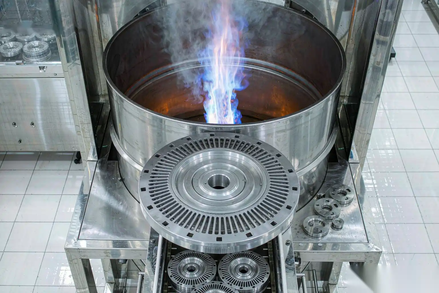
Thermal deburring, formally the thermal energy method (TEM), removes burrs by a controlled micro-detonation inside a sealed pressure chamber. The part, or a basket of parts, sits in the chamber. The machine injects a near-stoichiometric mixture of fuel gas and oxygen, then ignites it with a spark plug. The mixture burns in a few milliseconds. Peak gas temperatures reach roughly 1,800 to 3,000 °C for a dwell measured in milliseconds, yet the part itself stays below roughly 150 to 200 °C because the energy is absorbed by the burr, which has almost no mass, before it can conduct into the bulk casting.
The mechanism is not melting in the conventional sense. It is rapid oxidation at the burr root. A burr on a die cast part is a thin fin of metal, often 0.05 to 0.4 mm thick, sometimes up to 1 mm on a heavy gate scar, with a very high surface-area-to-volume ratio. When the combustible mixture ignites, the oxygen in the hot gas reacts with the exposed burr surface faster than heat can spread into the parent material. The burr oxidizes and is effectively vaporized or converted to a loose oxide powder at its thinnest section, which is the attachment to the part. The bulk casting, being massive by comparison, sheds the heat to the chamber walls and the gas without rising through its melting point.
This is the single property that makes TEM useful: it is geometry-blind at the burr level. A robot with a spindle or a brush can only reach what a tool can physically touch. TEM reaches every internal surface where the detonation gas can flow, including cross-holes, blind cavities, and intersecting bores that no end effector can enter. For die cast plumbing bodies, hydraulic manifolds, and fuel-system parts, that reach is the difference between a reliable process and a hand-finishing bottleneck.
Combustion physics: why the burr burns but the part survives

The survival of the part depends on the thermal mass ratio. Consider a burr fin 0.2 mm thick and 5 mm long on an aluminum A380 bracket. Its mass is on the order of 10⁻⁵ kg. The bracket it sits on might be 200 g. The ratio is about 1 to 20,000. When the gas temperature spikes, the fin reaches ignition and oxidation temperature almost instantly. The bracket absorbs the same heat flux across a surface area millions of times larger in mass and simply warms by a few degrees. The heat equation works in the process’s favor because the thin fin has almost no thermal inertia.
Two parameters dominate the process window:
- Fuel selection. Hydrogen plus oxygen is the most common industrial pairing because the flame is clean and leaves minimal carbon residue. Methane, natural gas, or propane blended with oxygen are also used where hydrogen supply is impractical. Hydrogen/oxygen mixtures produce water vapor as the primary combustion product; hydrocarbon fuels add CO₂ and water plus some carbon soot that must be washed off later.
- Mixture ratio. The chamber is charged to a target pressure, typically 2 to 8 bar absolute depending on part size and chamber volume, then a fuel fraction is added. For aluminum, a slightly oxygen-rich mixture, around 1.0 to 1.3 times stoichiometric, ensures complete burr oxidation. Too lean and the burr is only partially removed; too rich and carbon fouling increases and the oxide film thickens.
The ignition event is brief, on the order of 5 to 20 ms of active combustion, followed by a fast vent and purge. The part never sees a sustained high temperature. In practice we measure bulk part temperature with a contact probe after the cycle and rarely see it exceed 80 to 150 °C on thin-walled castings, and well under 100 °C on most zinc parts. That temperature band is far below the annealing or distortion range for both aluminum and zinc die castings, so dimensional change from the TEM event itself is negligible.
Geometries TEM wins on
The clearest wins are internal and intersecting features that defeat mechanical tooling. Table 1 lists the geometry classes and the reason TEM is preferred over a robotic or brush approach.
| Geometry | Why robots struggle | TEM result | Typical part examples |
|---|---|---|---|
| Cross-drilled holes (two axes intersect) | End mill or brush cannot enter the intersection zone | Burr at the crossover removed uniformly | Valve bodies, manifolds, hydraulic blocks |
| Blind internal cavities | No line of sight for spindle or brush | Full internal surface treated | Pump housings, sensor bores |
| Thin fins between ribs | Tool pressure risks gouging thin walls | No contact force, no gouge | Heat-sink-like castings, electronics enclosures |
| Internal parting-line flash | Flash sits below a ledge, unreachable | Gas reaches the ledge underside | Plumbing fittings, faucet bodies |
| Micro-burrs after drilling (<0.1 mm) | Robot repeatability cannot target reliably | Oxidation removes consistently | Fuel rails, injector seats |
A common example is a fluid manifold with three intersecting 6 mm bores. Mechanical deburring would require a custom cross-hole brush tool, a dedicated fixture orientation for each bore axis, and still leaves a residual crown at the intersection. TEM treats all three intersections in one cycle with no tool wear. On parts like these, TEM is not a luxury; it is the only method that removes the burr without designing a bespoke reach tool.
Where TEM does not help is external accessible flash on large flat faces, or burrs attached to surfaces you intend to keep dimensionally pristine. The oxidation leaves a thin, dulled oxide layer that usually needs washing or light blasting afterward. TEM should be specified for the internal problem, not as a blanket replacement for every edge in the cell.
Alloy limits and safety: aluminum, zinc, magnesium
Not every die cast alloy is equally suited to TEM. The deciding factors are melting point, oxidation behavior, and whether the part contains open porosity that would trap the gas mixture and produce a visible residue spot.
| Alloy family | TEM suitability | Key caution | Practical notes |
|---|---|---|---|
| Aluminum (A380, A360, ADC12) | Excellent | Open porosity vents gas, may dull surface | Most common TEM application |
| Zinc (Zamak 3/5, ZA8) | Very good | Lower melt point, keep mixture modest | Clean, low residue |
| Magnesium (AZ91D, AM60) | Restricted | High flammability, needs oxygen-lean mix | Often excluded from standard cells |
| Copper-based | Limited | Heavy oxidation possible | Rare in die casting |
Aluminum is the workhorse. The risk is not the bulk part but porosity. Die cast aluminum is inherently somewhat porous; if the porosity is open to the surface, the ignition gas can penetrate and the post-burn residue may appear as a darkened spot. We specify a pre-inspection for critical sealing faces and, on leak-path parts, sometimes pair TEM with a subsequent pressure-decay test so a hidden residue lip does not compromise a seal.
Zinc die castings deburr cleanly and tolerate the thermal event well because their mass and melting range handle the brief heat without distortion. The main job is residue removal; zinc oxide is a fine white-to-grey powder that must be washed off before plating or painting. Because zinc has a lower melting point than aluminum, around 380 °C versus 595 °C for A380, the mixture is tuned slightly leaner and the charge pressure kept toward the lower end of the 2 to 8 bar band.
Magnesium demands respect. Magnesium ignites near 450 °C in air and burns vigorously once started. In a TEM chamber the gas mixture must be carefully controlled, often oxygen-lean or run with an inert buffer, and the part loading density limited so the event cannot sustain combustion. Many job shops simply exclude magnesium from their standard TEM cycle and route it to robotic or vibratory deburring instead. At DZ we treat magnesium on a case-by-case engineering review rather than as a default process, and we will tell a customer directly when a part should not go through TEM.
Cycle time, media cost, and throughput economics
TEM is a batch process, not a single-part continuous one, which shapes its cost profile and its place in the line.
A representative cycle for a basket of aluminum brackets breaks down as follows:
- Chamber fill and gas charge: 8 to 15 s
- Ignition and combustion: under 1 s
- Vent, purge, and door open: 10 to 20 s
- Basket load or unload, manual or indexed conveyor: 15 to 40 s
Total per basket lands around 40 to 90 s, and a basket may hold 10 to 50 small parts depending on envelope. That is roughly 400 to 3,600 parts per hour at the chamber, before loading labor. There is no abrasive media to buy; the consumable is fuel gas and electricity. A hydrogen/oxygen TEM cell typically consumes on the order of 0.2 to 1.0 m³ of gas mixture per cycle depending on chamber volume, which at industrial gas pricing is a few cents to a few tens of cents per basket.
Compare that to robotic grinding, where media cost is low but cycle time is per-part and tool wear is a real recurring expense. The crossover is usually:
- Use TEM when the burr is internal or unreachable and the part volume justifies a batch chamber.
- Use robotic deburring when burrs are external and accessible, the part is large, or you need to hold a tight dimensional window on the same feature you are cleaning.
Media and tooling cost for robotic cells includes abrasive belts at roughly $2 to $15 each lasting 200 to 2,000 parts, and grinding wheels or brushes replaced every shift to every few days. TEM avoids that line item but adds gas supply and chamber maintenance, seal replacement every 6 to 12 months, and ignition plug wear. The two processes are not competitors on cost alone; they are competitors on reach, and reach is what decides the routing.
Where TEM complements rather than replaces robotic deburring in a DZ cell
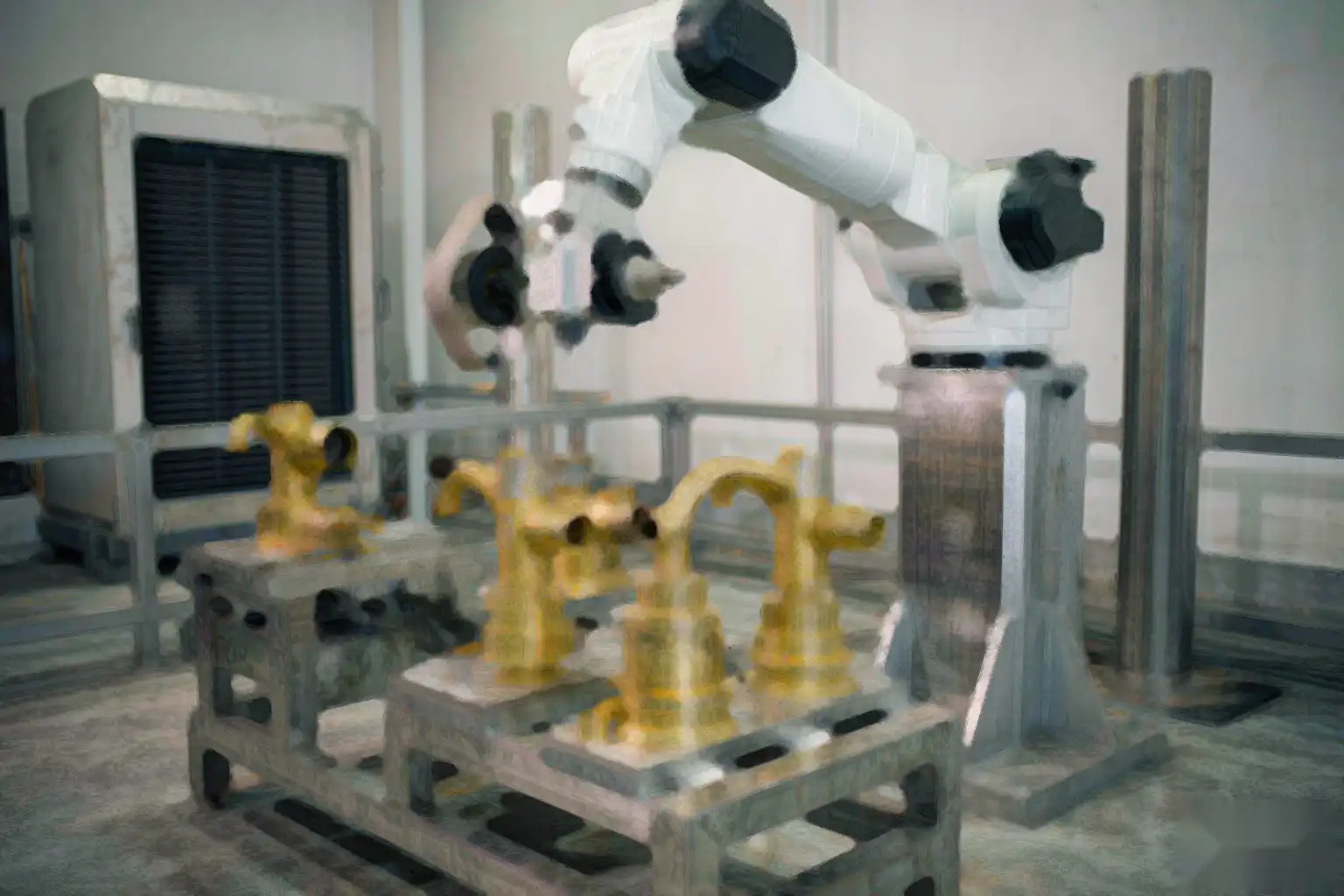
The productive question is not “TEM or robot” but “TEM and robot in what order.” A hybrid finishing cell from DZ typically sequences the operations so each technology does what it is best at:
- Robotic deburring removes the large external gate scars and parting-line flash that dominate cycle time if left to TEM.
- TEM clears the internal cross-hole burrs and blind-cavity fins the robot cannot reach.
- A wash or light vibratory or blast stage removes oxide residue.
- Robotic polishing or brushing restores the external cosmetic surface where needed.
This division of labor matters because TEM alone is slow at big external flash and leaves a matte oxide, while robots alone cannot reach internal intersections. In a DZ cell we mount the TEM chamber as a station on the same conveyor or rotary index as the robotic grinders, so a single part flows through without manual re-fixturing. The fixture design for the robot stage and the basket design for the TEM stage are engineered together so locating datums survive the transfer, and the datum and clamp strategy is planned up front rather than after the fact. When you are laying out a die casting secondary operations guide the ordering of TEM versus robot is one of the first decisions we make with a customer, because it sets the fixture, the wash step, and the cell footprint.
For shops already running automated aluminum deburring, adding a TEM station is usually a small footprint change that unlocks a class of parts they previously finished by hand. The robot does the 80 percent of edges it can see; TEM does the 20 percent it cannot. Together they remove the manual bench entirely.
Acceptance, residues, and post-TEM cleaning
After the detonation the part carries three things:
- Loose oxide powder on the burr location.
- A dulled, slightly oxidized surface film over treated areas.
- Possible light carbon residue if the mixture was rich or a hydrocarbon fuel was used.
Acceptance is usually visual plus a tactile or fiber test: a nylon probe or gauze should not catch at the former burr edge. For sealing surfaces we add a bubble or pressure-decay test because the dulled oxide can mask a residual lip that later leaks. A calibrated go/no-go probe through the cross-hole is also common for fluid parts.
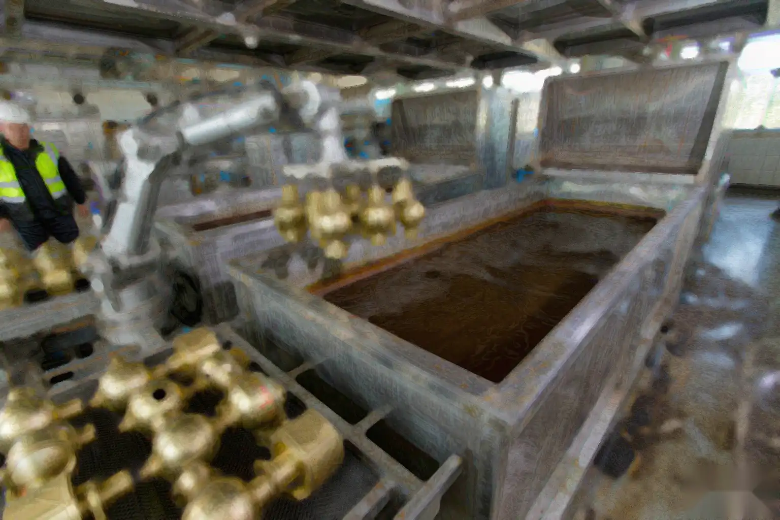
Cleaning is mandatory before plating, anodizing, or painting. Options in order of aggressiveness:
- Aqueous wash with a mild alkaline cleaner, 40 to 60 °C, 30 to 90 s.
- Light media blast, glass bead 50 to 150 µm, for parts that will be cosmetic.
- Ultrasonic clean for internal passages where loose powder must be evacuated.
We do not ship TEM-treated parts to a coating line without a wash stage in the cell, because the oxide film interferes with adhesion and a trapped powder pocket will later bleed out as a surface defect. The wash step is part of the process window, not an afterthought.
Design rules that make TEM reliable
Engineers can reduce TEM risk at the drawing stage, and most of the rules are about giving the gas a path and the robot a first cut:
- Avoid designing trapped gas pockets with no vent path; the mixture must reach and clear the burr.
- Keep sealing faces away from heavy internal flash where possible, or plan a follow-up machining pass.
- Specify burr limits realistically; TEM handles 0.05 to 1.0 mm burrs well, while a 3 mm gate scar belongs to the robot first.
- For magnesium, flag the material on the drawing so the cell routes it to non-TEM deburring.
- Consider draft and parting-line location so flash forms where a robot can take the first cut, leaving only internal micro-burrs for TEM.
- Dimension internal intersections with a small radiusing allowance if the customer process allows, because a sharp crossover is where the residual crown hides.
When the part is designed with this split in mind, TEM becomes a fast, low-media-cost finishing step rather than a rescue operation.
When to bring DZ into the cell design
DZ Machinery builds integrated deburring and finishing cells that combine six-axis robotic grinding with thermal energy method stations and downstream wash or polish, engineered around your part geometry and alloy. If you have die cast parts with internal cross-holes, blind cavities, or burrs a robot cannot reach, send us your part drawings and we will model the cell layout, cycle balance, and residue-cleaning step so the line meets your throughput and surface targets.