Burrs on metal castings are more than a cosmetic flaw. They cause assembly failures, cut injuries to handlers, and trigger customer rejections that cost foundries thousands every month. For finishing managers and foundry operators, removing these burrs efficiently is a persistent bottleneck — especially as skilled labor becomes harder to find and retain.
An automatic deburring machine solves this problem at the root. But how does it actually work? This guide walks through the entire process: how the machine detects burrs, which robotic tools remove them, the sensing technology that prevents over-cutting, and how leading foundries are deploying these systems today. Whether you work with brass, aluminum, zinc, or iron castings, you’ll walk away with a clear understanding of what automated deburring can deliver for your production floor.
What Is an Automatic Deburring Machine?
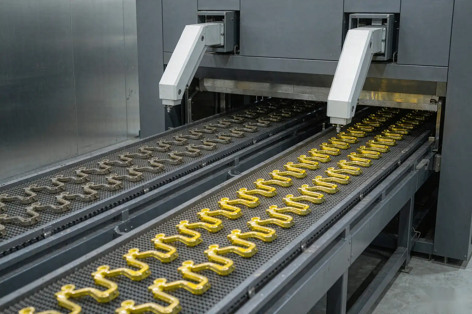
An automatic deburring machine is a robotic or CNC-controlled system engineered to remove sharp edges, parting line flash, gate vestiges, and other burrs from metal castings without manual intervention. Unlike hand grinding or manual deburring stations — where quality depends entirely on the operator’s skill and stamina — these machines use programmed toolpaths, real-time force sensing, and specialized cutting tools to deliver consistent, repeatable results on every single part, across every shift.
These systems are deployed in foundries worldwide processing brass, zinc alloy, aluminum alloy, and iron castings. Key end-user industries include:
- Sanitary ware and plumbing fixtures
- Automotive powertrain and chassis components
- Aerospace structural castings
- General hardware and industrial equipment
- Hydraulic and valve systems
Industry data shows that automated deburring can reduce finishing labor costs by 50–70% while improving throughput by 2–4× compared to manual operations [Source: Foundry Management & Technology, 2025 Finishing Benchmark Report].
Why Castings Need Deburring: The Hidden Cost of Burrs
When molten metal is poured into a die or mold, parting lines, cores, and gating systems inevitably leave unwanted material on the casting. These burrs appear in several distinct forms:
- Parting line flash — Thin fins of metal along the mold split line
- Gate vestiges — Leftover material from the pouring channel where the sprue was cut
- Core shift burrs — Raised edges where cores shifted during the casting process
- Ejector pin marks — Small raised bumps from the ejection mechanism
- Sharp edges — Created by trimming, cutting, or secondary operations
If left untreated, these burrs create real business problems:
- Assembly failures — Parts with burrs won’t mate correctly, jamming production lines
- Safety hazards — Sharp burrs cause injury to handlers and end users (OSHA recordable incidents)
- Coating defects — Burrs interfere with plating, painting, and powder coating adhesion
- Structural weaknesses — Sharp edges create stress concentration points that lead to cracking under load
- Customer rejection — Burrs violate most commercial casting standards (ASTM, ISO, DIN), triggering returns and rework at 3–5× the original finishing cost
The cost of rework alone can reach 15–25% of total casting production cost in foundries that rely on manual deburring [Source: American Foundry Society, 2024 Finishing Cost Analysis].
How Does an Automatic Deburring Machine Work?
An automatic deburring machine operates through a synchronized sequence of robotic movement, adaptive sensing, and precision tool engagement. Here is a step-by-step breakdown of the core process:
1. Part Loading and Positioning
The casting arrives at the worktable — either manually by an operator or automatically via a conveyor, gantry, or robot loading system. Most robotic deburring cells use a rotary index table or pallet conveyor that positions the part within the robot’s reach envelope. The part is clamped securely using pneumatic fixtures, vise grips, or custom machined nests designed to match the casting geometry within ±0.1 mm tolerance.
2. Robotic Arm and End-Effector Setup
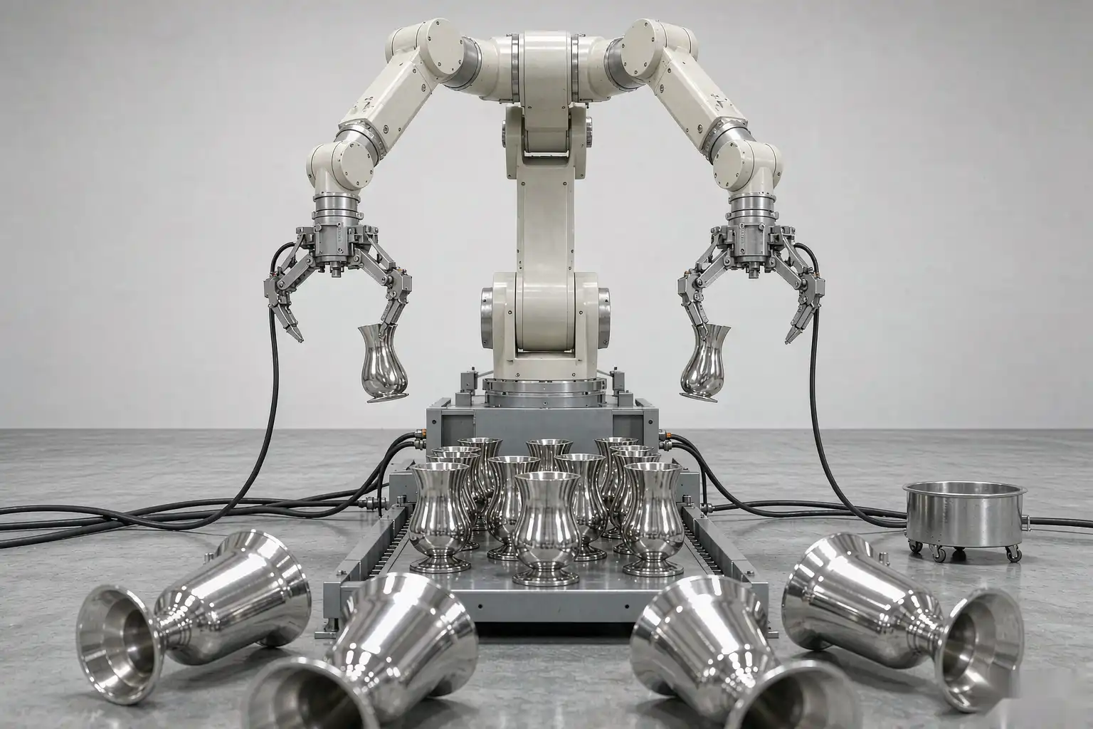
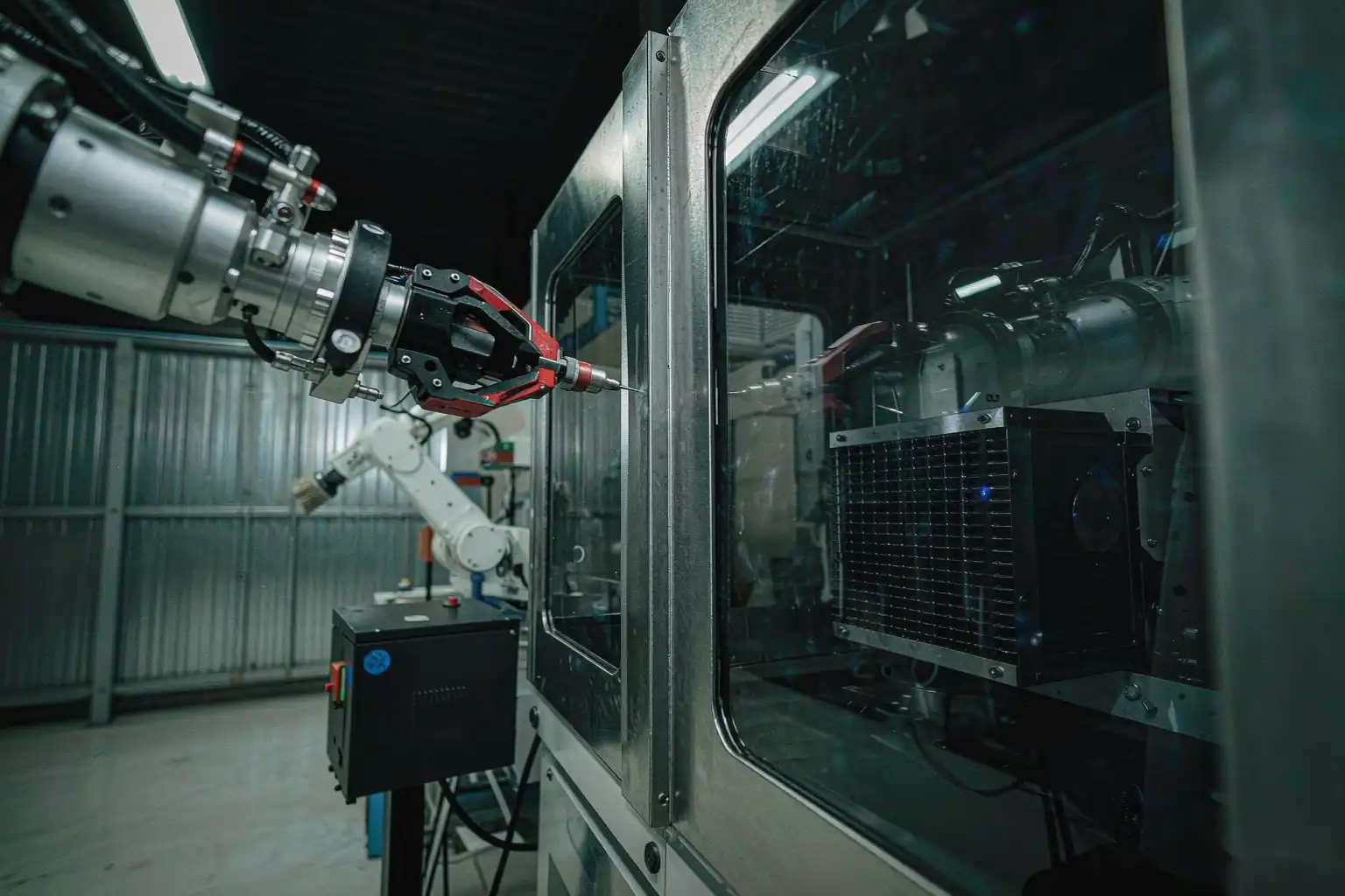
A six-axis industrial robot (typically payload 10–50 kg, reach 1.4–2.0 m for castings) carries the deburring tool through the programmed path. In some cell layouts, the robot holds the part and presents it to a stationary tool. The robot’s six-axis articulation provides the flexibility to reach complex internal cavities, angled parting lines, and curved surfaces that manual tools cannot access consistently.
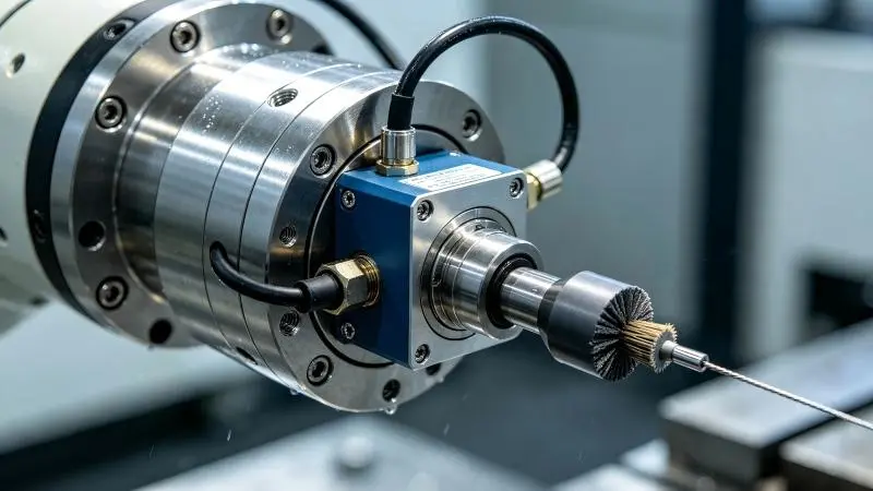
Common end-effectors include:
- Pneumatic/electric spindles with carbide or PCD burrs — heavy flash removal
- Compliant abrasive brushes (nylon with silicon carbide or steel wire) — edge breaking and surface finish
- Floating deburring heads — self-align along irregular edges
- Robotic files and abrasive belts — flat surface deburring and gate removal
- Ceramic fiber tools — internal passage and cross-hole deburring
3. Adaptive Force Control and Real-Time Sensing
This is the technology that makes robotic deburring practical for castings. The robot is equipped with a six-axis force-torque sensor mounted between the wrist flange and the tool. This sensor measures contact forces in all directions at a sampling rate of 1,000 Hz or higher.
Here’s what happens in real time:
- The tool makes contact with the casting edge
- The force sensor detects the contact force (typically 5–50 N depending on material and burr size)
- When the tool encounters a burr, resistance spikes
- The control system compensates instantly — adjusting the robot’s path to apply sufficient force to remove the burr
- When the burr is gone, resistance drops, and the robot returns to the baseline path — zero gouging of the base material
Advanced systems also integrate:
- 3D vision systems — to locate the part in the workcell and compensate for position variation
- Laser profile scanners — to map casting dimensional variation before deburring begins
- Spindle load monitoring — to detect tool wear and trigger automatic tool changes
- In-line force logging — to provide quality documentation for every part deburred
4. Programming the Deburring Path
The robot is programmed using one of three methods, depending on part complexity and production volume:
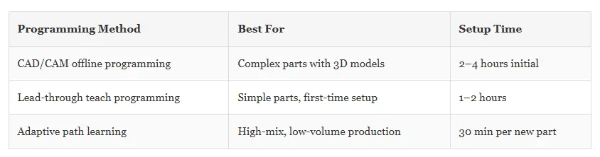
For complex castings requiring multiple operations — rough deburring, fine edge breaking, and surface blending — the robot switches between tools automatically using an automatic tool changer, completing all operations in a single cycle.
5. The Complete Deburring Cycle
A typical cycle runs through these stages:
- Part arrives at the station (manual or automated loading, 3–8 seconds)
- Clamping system secures the casting in position (2–3 seconds)
- Robot moves to the first deburring position with the appropriate tool (1–2 seconds)
- Tool engages the edge; force sensor maintains consistent contact pressure throughout the path
- Robot follows the programmed path along all parting lines, gates, and edges (15–60 seconds, depending on part size)
- Tool changes automatically via tool changer if multiple deburring operations are needed (3–5 seconds per change)
- In-process inspection verifies deburring quality (vision check or force log review)
- Part is released and indexed to the next station — grinding, polishing, or final inspection
Total cycle time for a typical brass casting (0.5–2.0 kg): 30–90 seconds, compared to 2–6 minutes for manual deburring.
Deburring Tool Selection by Material and Burr Type
Selecting the right tool for the job is critical. Here is the practical guide:
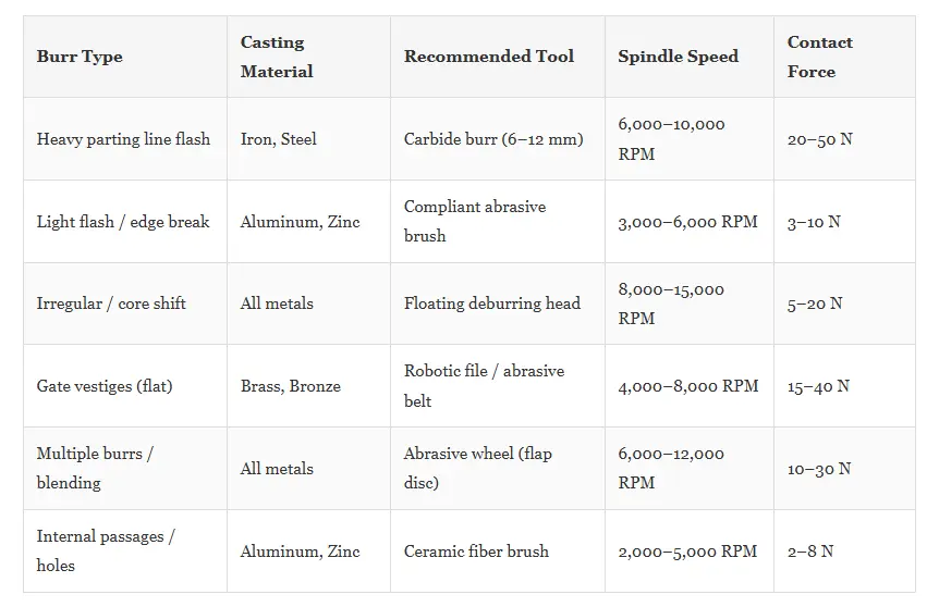
Deburring Approaches for Common Casting Materials
Different casting materials behave differently during deburring. An automatic deburring machine adjusts its parameters — spindle speed, contact force, feed rate, and tool selection — based on the specific material:
Brass and bronze castings: Relatively soft, but burrs can be tough and stringy. Carbide burrs with moderate spindle speeds (8,000–12,000 RPM) and abrasive brushes work effectively. Force range: 15–30 N.
Aluminum alloy die castings: Soft material that tends to gall and smear. Compliant brushes and diamond-cut carbide burrs prevent surface damage. Lower force settings (3–10 N) and higher speeds are required.
Zinc alloy die castings: Very soft; burrs are thin and remove easily. Floating heads and light abrasive brushes deliver the best results. High speed, low force (2–8 N).
Gray iron castings: Hard and abrasive. Requires carbide or PCD-tipped tools with higher force (20–50 N) and slower feed rates. Ceramic fiber tools work well for internal edges.
Ductile iron castings: Tough and resilient. Heavy-duty spindles (3+ kW) and robust robotic arms (50 kg+ payload) are needed. Multiple passes may be required for thick flash sections.
7 Key Benefits of Automated Deburring for Foundries
Switching from manual to automated deburring delivers measurable, data-backed improvements:
1. Consistent quality — every part, every shift. A robotic deburring machine for castings removes burrs to the same standard on every single part. No variation between operators, no end-of-shift fatigue, no missed edges. Quality consistency improves from ±30% variation (manual) to ±3% (automated).
2. 2–4× higher throughput. Automated deburring cycles are significantly faster than manual work for complex castings. The machine runs continuously without breaks, shift changes, or lunch periods.
3. Eliminated labor dependency. With skilled finishing workers becoming harder to find — the manufacturing labor shortage is projected to reach 2.1 million unfilled positions by 2030 in the US alone (Deloitte/NAM) — automating eliminates reliance on manual labor for this physically demanding and repetitive task.
4. 30–50% reduction in scrap and rework. Force-controlled deburring prevents over-cutting, gouging, or damaging the casting. The force sensor ensures only the burr is removed, not the parent material. This directly reduces scrap rates and rework costs.
5. Improved operator safety. Workers no longer handle sharp burrs, flying metal debris, or vibrating hand tools. The robot operates inside a guarded cell with interlocked access doors, eliminating the risk of lacerations and repetitive strain injuries.
6. Flexible production across multiple part families. A single automated deburring solution can handle 10–50+ different casting types. Changeover between parts takes 3–5 minutes with quick-change fixtures and program recall.
7. Documented quality assurance. Every part deburred by an automated system can be accompanied by force logs, cycle time data, and optional vision inspection records — providing traceable quality documentation for ISO 9001 and customer audit requirements.
How to Select the Right Automatic Deburring Machine for Your Foundry
Choosing the right automatic deburring machine requires evaluating five key factors:
1. Part size and weight
- Parts under 5 kg: Compact cells with index tables are cost-effective
- Parts 5–30 kg: Standard six-axis robot cells with custom fixtures
- Parts over 30 kg: Dual-robot cells or gantry-based systems for heavy castings
2. Production volume
- High volume (2,000+ parts/day): Dedicated robotic cell with automated loading, tool changers, and in-line inspection
- Medium volume (500–2,000 parts/day): Flexible cell with manual loading and quick-change tooling — best ROI at 12–18 months
- Low volume / mixed production (< 500 parts/day): Flexible cell with vision-guided programming and quick-change fixtures
3. Burr complexity
- Simple parting line flash: Floating deburring head only
- Moderate burrs (flash + gate vestiges): Spindle + brush combination
- Complex burrs (internal edges, cross-holes, threads): Multiple tool changes, vision-guided path, and optional secondary operations
4. Material hardness
- Iron and steel: High-torque spindles (2–5 kW), rigid robot arm (50 kg+), carbide/PCD tools
- Aluminum and zinc: Standard spindles (1–2 kW), smaller robot (10–20 kg), compliant tools
5. Integration requirements
- Standalone cell: Ideal for retrofit into existing production lines
- Turnkey system: Includes pre-programmed paths, conveyors, and safety guarding for new lines
- Fully integrated line: Combines deburring with upstream casting and downstream grinding/polishing
Frequently Asked Questions
How long does it take to program an automatic deburring machine?
For simple castings, initial programming takes 1–2 hours. Complex parts with multiple deburring requirements may take 4–8 hours. Modern CAD-to-path software reduces this to under 30 minutes for parts with a 3D model available.
Can an automatic deburring machine handle different part sizes?
Yes. Most robotic deburring cells accommodate a range of part sizes within the robot’s reach envelope and payload capacity. Flexible fixturing and quick-change tooling allow switching between different castings in under 5 minutes.
What is the typical ROI period for an automatic deburring machine?
For medium-volume foundries (500–2,000 castings per day), typical ROI is 12–18 months. Higher-volume operations achieve ROI in under 12 months. Key drivers: direct labor savings (typically 50–70% reduction), reduced scrap (30–50% decrease), and increased throughput (2–4× improvement).
Does robotic deburring damage the casting surface?
No — when properly programmed. Force-controlled deburring robots use six-axis sensors measuring contact at 1,000 Hz. Unlike manual deburring, the robot maintains consistent pressure and does not over-cut or gouge the surface. The result: only the burr is removed, with no measurable impact on the base material (±0.02 mm depth accuracy with force control engaged).
What certifications do automatic deburring machines meet?
Leading automated deburring solutions are designed to integrate into ISO 9001:2015 quality management systems, meet ANSI/ISO 10218 robot safety standards, and comply with CE and UKCA machinery directives. Systems can generate force-log quality documentation for every part deburred.
Conclusion
An automatic deburring machine transforms the finishing stage of casting production. By combining six-axis robotic precision, high-frequency force sensing, and material-matched tooling, modern foundries can eliminate the inconsistency, safety risks, and labor dependency of manual deburring — while achieving higher throughput and significantly lower scrap rates.
Whether you produce brass faucets, aluminum die castings, gray iron components, or ductile iron parts, the core working principle is the same: the robot follows a programmed path, adapts to the material in real time through force feedback, and removes burrs with repeatable precision — part after part, shift after shift.
Visit grindermachinepolish.com to schedule a process evaluation or contact directly on LinkedIn for a sample-run quotation.